EasyManua.ls Logo

Woodward ProTech-GII 8237-1597 - User Manual

Woodward ProTech-GII 8237-1597
207 pages
Print Icon
To Next Page IconTo Next Page
Loading...
®
Product Manual 26709
(Revision F, 10/2016)
Original Instructions
ProTech-GII Overspeed Protection Device
with Voted Inputs
8237-1594, -1595, -1596, -1597, -1598, -1599,
-1600, -1601, -1656, -1660
Installation and Operation Manual

Table of Contents

Questions and Answers

  • J
    James BakerAug 14, 2025
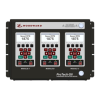
    How to troubleshoot power supply input alarm on Woodward ProTech-GII 8237-1597 Security Sensors?
    • C
      Christopher PowersAug 14, 2025
      If the Woodward Security Sensors power supply inputs aren't working and a power supply input alarm is present, check the wiring and terminal block connections to ensure they are secure. Verify that the breaker or fuse for the power source is not open. Confirm that you have at least two power supplies connected. On the front panel, press the VIEW button under the ALARM LED and check for Power Supply 1 or 2 Fault. Check the input voltage level to ensure it's within the acceptable range according to the electrical specifications, and verify the power supply has the appropriate rating to power the ProTech-GII.
  • D
    Daniel SpearsAug 17, 2025
    What to do if trip relays are not working on Woodward Security Sensors?
    • T
      Tyler PerezAug 17, 2025
      If the trip relays on your Woodward Security Sensors are not working, check the wiring and terminal block connections. Using the Programming and Configuration Tool or front panel, verify that the trip configuration is set correctly, considering that energize-to-trip versus de-energize-to-trip inverts the polarity on the relays. Check the power supplies that provide voltage to the relay output. If you are using the 24 V EXT available from the ProTech-GII, measure the voltage between terminals 80 and 81 to ensure it is 24 V ±10%. If it is not, remove the wiring from the 24 V EXT to unload the output and measure again to verify the voltage is not being overloaded.
  • M
    Megan ShepardAug 21, 2025
    How to fix Woodward ProTech-GII 8237-1597 speed input not working?
    • D
      davidnunezAug 21, 2025
      If the speed input on your Woodward Security Sensors is not working, verify the wiring and terminal block connections. On the front panel, check the Speed Input Configure Menu to ensure all configuration options are correctly selected. Verify there are no alarms or faults indicating a setup problem, such as open wire trip, speed lost, or speed fail. Ensure the input signal levels are within the electrical specifications and check the shield connections. If using an active probe, disconnect it and measure the voltage from terminals 69 to 71; it should be 24 V ±10%. Reattach the probe and measure again to verify it is not overloading the voltage provided by the ProTech-GII.
  • M
    Mark HansenAug 25, 2025
    Why is the alarm relay output not working on Woodward ProTech-GII 8237-1597 Security Sensors?
    • N
      Nicole MorganAug 26, 2025
      If the alarm relay output on your Woodward Security Sensors is not working, check the wiring and terminal block connections. Inspect the power supplies that provide voltage to the relay output. If you're using the 24 V EXT available from the ProTech-GII, measure the voltage between terminals 80 and 81 to verify it's 24 V ±10%. If it is not, remove the wiring from the 24 V EXT to unload the output and measure again to verify the voltage is not being overloaded.
  • C
    cherylpattersonAug 28, 2025
    What causes dedicated discrete input malfunction in Woodward ProTech-GII 8237-1597?
    • C
      Caitlyn JacksonAug 28, 2025
      If a dedicated discrete input (Start, Reset, or Speed Fail Override) on your Woodward Security Sensors is not working, verify the wiring and terminal block connections. On the front panel, check the Dedicated Discrete Inputs Monitor Menu and ensure the logic state is correct. Check the signal level to confirm it's within the acceptable range per the electrical specifications. Measure the voltage from terminal 1 to terminal 81; it should be 23 V ±2 V. If it is out of range, return the unit to Woodward.
  • E
    edwardscynthiaSep 1, 2025
    How to troubleshoot analog output issues on Woodward ProTech-GII 8237-1597?
    • P
      Paul JonesSep 1, 2025
      If the analog output on your Woodward Security Sensors is not working, verify the wiring and terminal block connections. On the front panel, check the Monitor Analog Output Menu and ensure that the analog output is reading an expected output value. Measure the current from terminal 64 and verify it corresponds to the previous step. Verify the load on the analog output is within the electrical specifications. Using the PCT or front panel, verify the scaling is correct.
  • T
    Timothy BrockSep 5, 2025
    What to check if MODBUS is not functioning on Woodward ProTech-GII 8237-1597 Security Sensors?
    • D
      David TaylorSep 5, 2025
      If MODBUS is not working on your Woodward Security Sensors, verify the wiring and terminal block connections. Specifically, ensure the HI and LO wires are terminated to the correct terminals for RS-485, and likewise for TXD and RXD for RS-232. Also, verify the termination jumpers are installed for RS-485 mode. Using the PCT or front panel, verify the correct settings are selected.
  • E
    elizabethwatsonSep 9, 2025
    How do I fix a Programming and Configuration Tool issue with Woodward Security Sensors?
    • S
      stephanie13Sep 9, 2025
      If the Programming and Configuration Tool is not working with your Woodward Security Sensors, verify that the cable plugged into the DB9 port is not a crossover cable; a straight-through cable is required. Check that power is applied to the ProTechTPS module and that the service tool is connected. Verify the correct COM port is selected when establishing communications and that Auto Detection BAUD rate is selected.

Summary

Chapter 2. Installation

Hardware Installation Procedure

Step-by-step guide for physical installation and initial setup.

Module Removal and Installation-Bulkhead Mount Package

Step-by-step guide for removing and installing bulkhead mount modules.

Module Removal and Installation-Panel Mount Package

Step-by-step guide for removing and installing panel mount modules.

Chapter 3. Functionality

Overspeed and Over-Acceleration Detection Logic

Explains the core detection mechanisms for overspeed and over-acceleration events.

Start Logic

Details the logic and functions related to starting the system.

Chapter 4. Front Panel Interface

Chapter 5. Configuration of the ProTech-GII via Front Panel

Editing Configuration Settings from the Front Panel

Details the process of modifying parameters directly on the device.

Configuration Procedure

Outlines the steps for configuring the device via the front panel.

Chapter 6. Test Routines

Chapter 7. Programming and Configuration Tool (PCT)

Using the Programming and Configuration Tool (PCT)

Guides on using the PCT for configuration via connected or disconnected modes.

Chapter 8. Modbus Communications

Chapter 9. Safety Management

Safe State and SIL Specifications

Details safe state configuration and SIL safety standards compliance.

Functional Testing after Initial Installation

Describes required tests after the initial installation.

Proof Testing (Functional Test)

Details periodic tests to ensure safety system integrity.

Chapter 10. Troubleshooting

I;O Troubleshooting

Addresses common issues with input/output signals.

Woodward ProTech-GII 8237-1597 Specifications

General IconGeneral
BrandWoodward
ModelProTech-GII 8237-1597
CategorySecurity Sensors
LanguageEnglish

Related product manuals