EasyManua.ls Logo

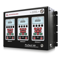
Woodward ProTech-GII User Manual

Woodward ProTech-GII
195 pages
To Next Page IconTo Next Page
Page #1 background imageLoading...
Page #1 background image
Product Manual 35086
(Revision -, 2/2018)
Original Instructions
ProTech-GII
Overspeed Protection Device
with Math Enhancements
Installation and Operation Manual
Released

Table of Contents

Other manuals for Woodward ProTech-GII

Questions and Answers:

Woodward ProTech-GII Specifications

General IconGeneral
Overspeed ProtectionYes
Processor32-bit microprocessor
ApplicationsGas turbines, steam turbines
Speed Inputs3
Self-DiagnosticsYes
Communication ProtocolsModbus RTU, Modbus TCP/IP
Operating Temperature Range-40°C to +70°C
MountingPanel mount
MemoryFlash memory
Protection FeaturesOverspeed, loss of speed signal
CertificationsCE, UL

Summary

Installation

Hardware Installation Procedure

Step-by-step instructions for physically installing the ProTech-GII device.

Power Supply Requirements

Specifications and requirements for powering the ProTech-GII unit.

Functionality

Overspeed and Over-Acceleration Detection Logic

How the device detects and responds to overspeed and over-acceleration events.

Speed Redundancy Manager

Configuration and operation of the speed signal redundancy system.

Front Panel Interface

Passwords

Details on the security levels and password management for device access.

Configuration Using the Front Panel

Editing Configuration Settings from the Front Panel

Procedure for accessing and modifying device parameters via the front panel.

Configuration Procedure

Step-by-step guide for configuring the ProTech-GII using its front panel.

Configure Test Modes Page

Settings for various system tests, including timeouts and permissives.

Configuration Management Menu Page

Options for managing configurations, including comparison and copying.

Test Routines

Temporary Overspeed Setpoint Test

Procedure for testing overspeed function with a modified trip setpoint.

Simulated Speed Tests

Performing tests using internally generated speed signals for validation.

Programming and Configuration Tool (PCT)

Connection Procedure

Steps to establish communication between the PCT software and the ProTech-GII.

Edit/View Configuration Button

Accessing and modifying module parameters using the PCT software.

Configuration Using the PCT

Configure Speed Input Page

PCT screen for configuring speed sensor, gear ratio, and trip parameters.

Speed Redundancy Management (RM)

PCT configuration options for managing speed signal redundancy.

Safety Management

Safe State

Defining the device's safe operating conditions and trip configurations.

SIL Specifications

Details on Safety Integrity Level (SIL) compliance and requirements.

Proof Testing (Functional Test)

Procedures for verifying system safety and functionality through periodic testing.

Troubleshooting

I/O Troubleshooting

Common issues with input/output signals and suggested solutions.

Related product manuals