FILLING THE SYSTEM
INSTALLATION & SERVICING INSTRUCTIONS FOR WORCESTER GREENSTAR HEATSLAVE EXTERNAL 12/18-18/25-25/32
8 716 113 389d (03/2010)
31
COMMISSIONING
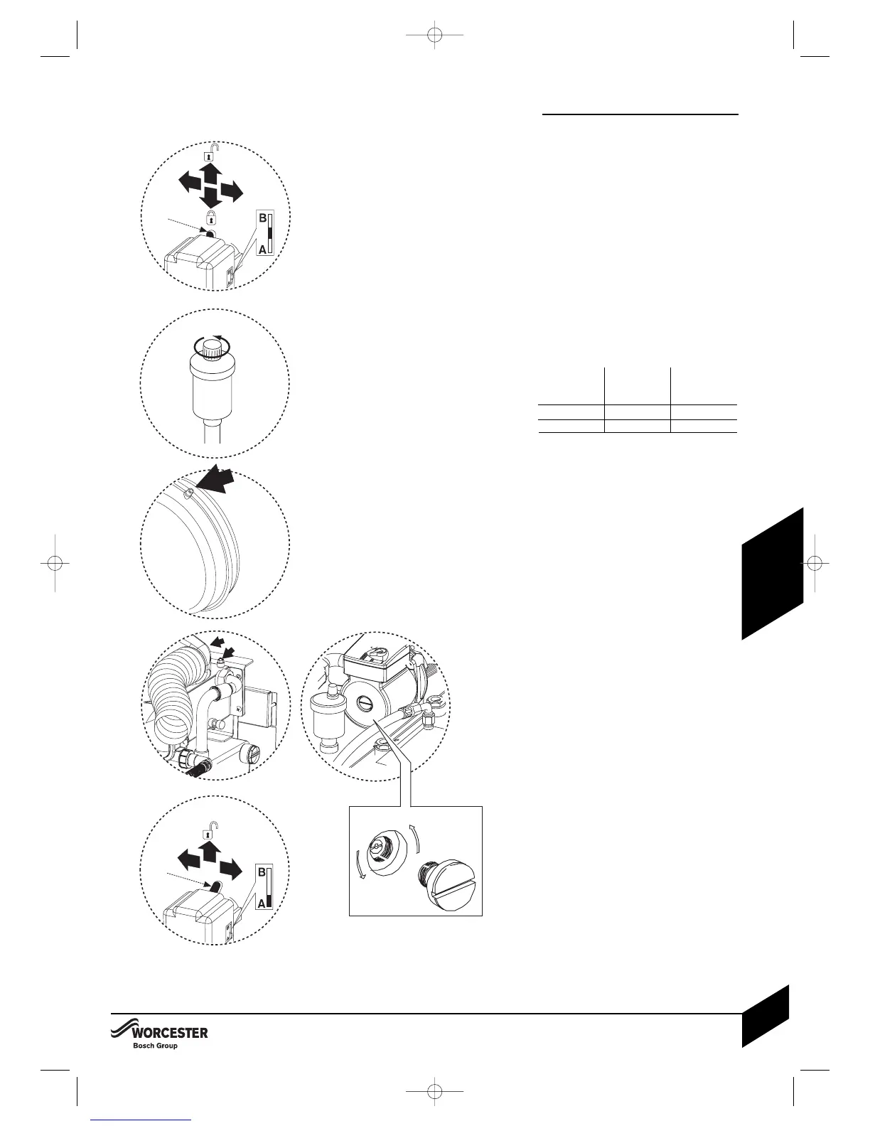
1Pull lever (C) up and push to the left to
move the diverter valve to the mid-position
between ports A and B.
Push and hold lever (C) down to lock.
2Loosen the automatic tank air vent.
The pump automatic air vent has a
protective cover that must remain in place,
this auto air vent needs no adjustment
before filling the boiler.
Refit the protective cover.
3Sealed systems only; check and if required,
adjust the expansion vessel pressure using
the Schraeder type valve (D).
The charge pressure of the built-in 12 Litre
expansion vessel is 0.5 bar as dispatched,
which is equivalent to a static head of 5m.
If an extra expansion vessel is fitted to the
central heating return, adjust this to the same
pressure as the appliance internal expansion
vessel, refer to separate instructions supplied
with the extra expansion vessel.
4Open all system and radiator valves (E).
Turn on the water main stop cock.
Open vented systems only; turn on the
water to the system feed and expansion
cistern and allow the system to fill.
Sealed systems only; fill the system to
between 1 and 2 bar pressure via a WRAS
approved filling link. Monitor the pressure
gauge during venting and repressurise if
required.
Check air is being discharged from the
automatic air vents.
Vent all radiators, retighten when completed,
check the system and correct any leaks.
Bleed air from both of the secondary heat
exchanger air vents (F).
Bleed air from the pump using the
pump bleed screw.
5Sealed systems only; connect a suitable
hose to the Heatslave tank drain. Open the
drain valve to reduce the system to the
correct pressure, then close the drain valve.
Ensure safe disposal of the discharge.
Rotate the adjustable pointer on the
pressure gauge to record the set system
pressure.
6 Check system and rectify any leaks.
Push lever (C) to the left and pull
upwards to allow the lever to return to
position A.
Leave the lever (C) unlocked at
position A.
FILLING THE SYSTEM
Total system
volume (litres)
180
107
138
Initial system
pressure (bar)
0.5
1.0
1.0
Initial charge
pressure (bar)
0.5
0.5
1.0