STARTING THE APPLIANCE
INSTALLATION & SERVICING INSTRUCTIONS FOR WORCESTER GREENSTAR HEATSLAVE EXTERNAL 12/18-18/25-25/32
8 716 113 389d (03/2010)
33
COMMISSIONING
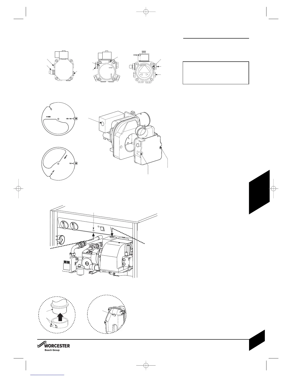
STARTING THE APPLIANCE
2 Remove plastic cover from the burner casing
(there is no plastic cover on the Riello burner).
Fit a suitable pressure gauge to port (A) on
the oil pump.
IMPORTANT: RIELLO BURNERS.
If changing the burner output, ensure the
position of the air damper disk is correct for
the desired output. Refer to the table on the
following page.
12/18 - RIELLO RDB 1
Adjust position of the air damper disc to suit
the burner output (see chart on the following
page), located as shown in the diagram
opposite. Access is by removing the two star
screws (SC) to release the air inlet manifold.
• 18/25 - RIELLO RDB 2.2
The damper disk should not be moved, as it
is required for all three outputs, 18, 21.5 and
25kW.
Adjust the air shutter (L) and pump pressure
(B) as shown in the table opposite. The
burner should ignite following a pre-ignition
period of approximately 15 seconds.
NOTE: The RIELLO control box has an
11 second delay before the start of
the pre-ignition.
Boiler lockout indicator on:
If the burner fails to establish a normal firing
pattern or flame failure occurs the flame
monitoring photocell mounted in the burner
body will alert the burner control box to shut the
burner down and provide a safe lockout state
indicated by the illumination of the
lockout indicator (E).
Wait 2 minutes then press the lockout
reset button (D) to initiate another start
sequence.
Repeat procedure until a flame is established.
3Start and run for 3 minutes then switch off.
Check for after-spurting from the nozzle,
indicated by oil saturation on the combustion
head (F).
If after-spurting occurs:
Release the burner retainers.
Remove the burner, combustion head (F).
and electrodes, hold the burner vertical
to unscrew the nozzle and fill the nozzle
holder with oil.
Refit nozzle, electrodes, combustion
head (F) and the burner.
Restart and run for 3 minute intervals until
after-spurting stops.
4Start and run for 20 minutes.
Remove sampling point plug (K) to check
the smoke reading is between 0-1. If the
smoke level is above 1, check the combustion
settings are correct and the oil nozzle is in
good condition.
NOTE: Smoke readings may be inaccurate until
the smoke from burning organic binder in
the access door insulation has ceased.