EasyManuals Logo

Worcester 12/18 User Manual

Worcester 12/18
56 pages
To Next Page IconTo Next Page
To Previous Page IconTo Previous Page
Page #42 background imageLoading...
Page #42 background image
INSPECTION AND SERVICE
Fire valve:
Check that the oil supply pipe has a fire valve
fitted at least 1m away from the appliance
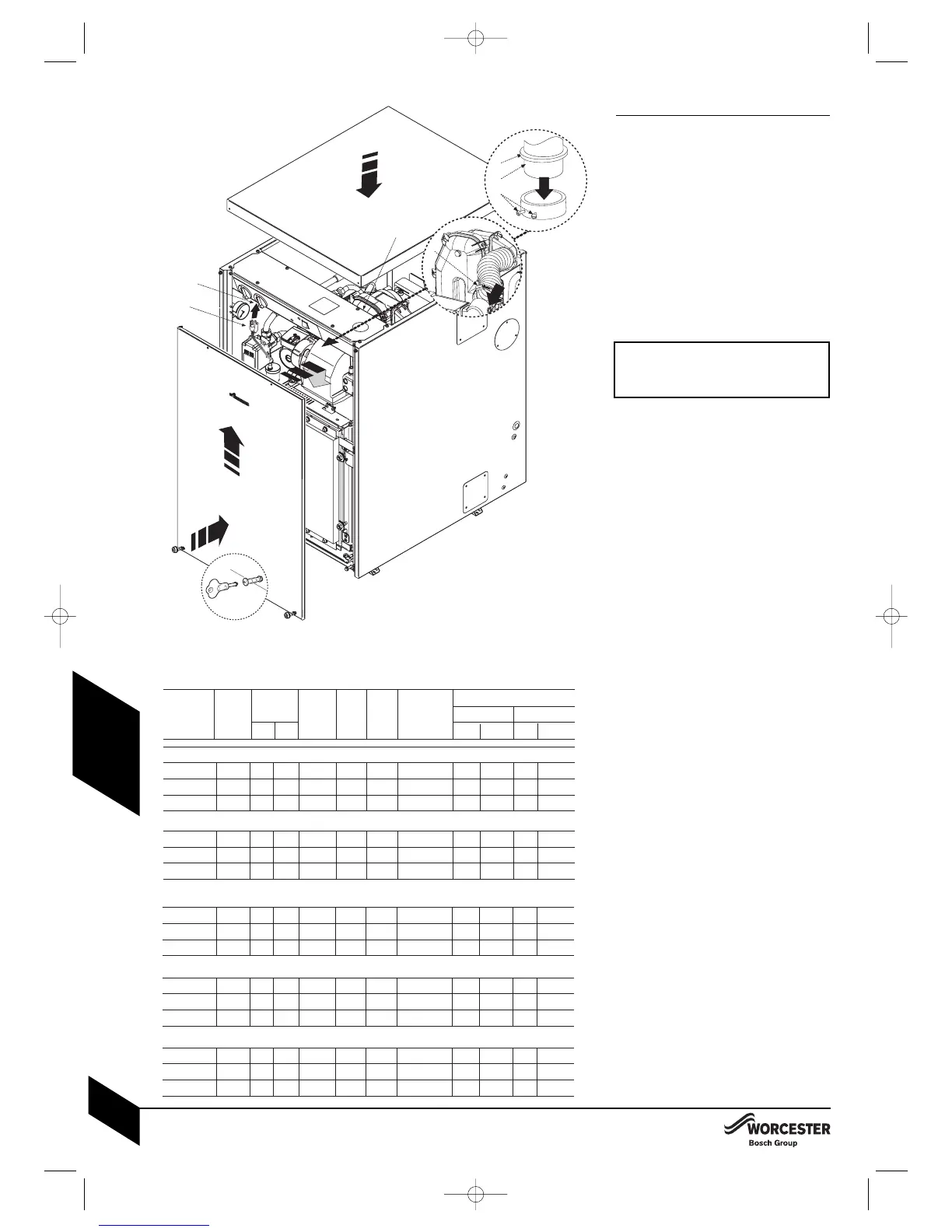
with the fire valve sensor located within the
appliance case. A fire valve sensor clip (A) is
provided for this purpose.
Re-commission the burner:
1Align burner combustion head (B) into the
boiler housing tube with gasket (C)
correctly fitted.
Push firmly down to compress the gasket (C).
Tighten burner retainers (D) sufficiently to
ensure a good seal.
IMPORTANT:
Ensure the gasket is a good seal between
the burner combustion head and the boiler
housing to prevent flue gases escaping.
Refit flexible air duct and secure with clip ( E ).
2Plug burner lead (F ) into control box (G).
Connect an oil pressure gauge to the oil
pump, run the burner and check the oil
pressure is correct for the required boiler
output. Check that the smoke reading is
between 0 and 1, if the smoke reading is
above 1 check the air setting. If the air
setting is correct check that the burner has
been reassembled correctly.
Allow the boiler to warm up then check the
combustion settings are correct as
indicated in the table below, adjust the
CO
2
if necessary using the air shutter.
When the combustion is correct turn off the
boiler, remove the pressure gauge and refit
the blanking plug and plastic cover.
Refit panels:
3Refit the top panel and press down to
compress the seal when fitting the
securing screws.
Push the front panel up behind the top
panel and push in at the base to secure
the screws with the tool provided.
After service handover:
Make a note of the date of any water treatment.
Set the controls back to the users
requirements.
Complete the service interval record at the
back of this manual and a CD11 or an
equivalent form.
If the appliance is unused and exposed to
freezing conditions; shut off all the mains
supplies, isolate the boiler and drain the
system and boiler, including the secondary
heat exchanger.
%CO
2
NOMINAL BOILER RATING AT NORMAL OPERATING TEMPERATURE
USING 28sec KEROSENE:
NOZZLE
12/18 - Bentone Sterling 40 Burner:
OIL
PUMP
PRESSURE
(p.s.i.)
FUEL
FLOW RATE
Kg/h l/h
APPROX
FLUE
GAS
TEMP.
( °C )
AIR
DAMPER
DISC
APPROX.
AIR
SETTING
APPLIANCE
INPUT OUTPUT
kW Btu/hr kW Btu/hr
0.35 80°SR
0.45 80°S
0.50 80°ES
115
115
140
1.04
1.29
1.55
1.32
1.63
1.96
66
70
73
11.5
12.0
12.5
2.5
4.5
5.25
42300
52900
63500
12
15
18
40900
51200
61400
12.4
15.5
18.6
12/18 - Riello RDB 1 Burner:
0.35 80°SR
0.45 60°ES
0.50 60°ES
105
120
125
1. 0 4
1.29
1.55
1.32
1.63
1.96
64
67
72
12 .0
12.0
12.5
4.5
3.0
4.5
42300
52900
6 3500
12
15
18
40900
51200
61400
12.4
15.5
18.6
18/25 - Riello RDB 2.2 Burner:
0.50 60°ES
0.65 60°ES
0.75 60°ES
125
120
115
1.56
1.86
2.17
1.98
2.36
2.75
75
78
84
11.5
12.0
12.5
2.0
3.0
4.5
63300
75100
8 9700
18
21.5
25
61400
73400
85300
18.6
22.2
25.8
25/32 - Riello RDB 2.2 Burner:
0.75 60°ES
0.75 60°ES
0.85 60°ES
105
140
150
2.15
2.45
2.75
2.72
3.10
3.48
78
80
83
11.5
12.0
12.5
3.0
4.0
5.0
87040
99200
111400
25
28.5
32
85300
97200
109200
25.5
29.1
32.7
18/25 - Bentone Sterling 50 Burner:
0.50 80°EH
0.55 80°EH
0.65 80°EH
130
145
150
1.56
1.86
2.17
1.98
2.36
2.75
72
79
82
11.5
12.0
12.5
4.25
6.0
8.0
63300
75100
87900
18
21.5
25
61400
73400
85300
18.6
22.2
25.8
N/A
N/A
N/A
N/A
N/A
N/A
15-18kW
15-18kW
12kW
18-25kW
18-25kW
18-25kW
N/A
N/A
N/A
3
1
2
3
F
A
C
B
D
F
INSPECTION AND SERVICE
INSTALLATION & SERVICING INSTRUCTIONS FOR WORCESTER GREENSTAR HEATSLAVE EXTERNAL 12/18-18/25-25/32
8 716 113 389d (03/2010)
42
SERVICING
& SPARES
E
G
8 716 113 389d 30/3/10 14:01 Page 42

Questions and Answers:

Question and Answer IconNeed help?

Do you have a question about the Worcester 12/18 and is the answer not in the manual?

Worcester 12/18 Specifications

General IconGeneral
BrandWorcester
Model12/18
CategoryBoiler
LanguageEnglish

Related product manuals