13. Expansion Vessel. Refer to Figs. 30,32.
Drain the central heating circuit as described in Section 16.3, a.
Hinge the facia panel into the servicing position as described in
Section 15.3, c.
Remove the gas to water heat exchanger, water to water heat
exchanger and pump as described in 16.4, 3,12 and 18 and
remove the vessel.
Fit the replacement vessel in the reverse order.
Open the valves and fill and re-pressurise the system as
described in Section 13.2
14. Pressure Relief Valve. Refer to Fig. 22.
Drain the central heating circuit as described in Section 16.3, a.
Hinge down the facia panel as described in Section 15.3, c.
Remove the bottom panel as described in Section 15.3, d.
Pull out the retaining clip and remove the pressure gauge
connection. Undo the discharge pipe connection and remove the
valve taking care not to distort the pipework.
Fit the replacement valve in reverse order. Reconnect the
discharge pipe.
Open the valves and fill and re-pressurise the system as
described in Section 13.2.
15. Water Diverting Valve Micro Switch Assembly.
Refer to Figs. 30,33.
Check that the electricity supply to the appliance is turned off.
Hinge down the facia panel as described in Section 15.3(c).
Remove the bottom panel as described in Section 15.3(d)
Using a pair of fine nosed pliers, pull the circlip off and remove
the micro switch assembly from the valve. Remove the black
cover and carefully pull off the connections from the terminals
on the micro switches.
Withdraw the switch assembly from the appliance.
Fit the replacement micro switch assembly in the reverse order.
21
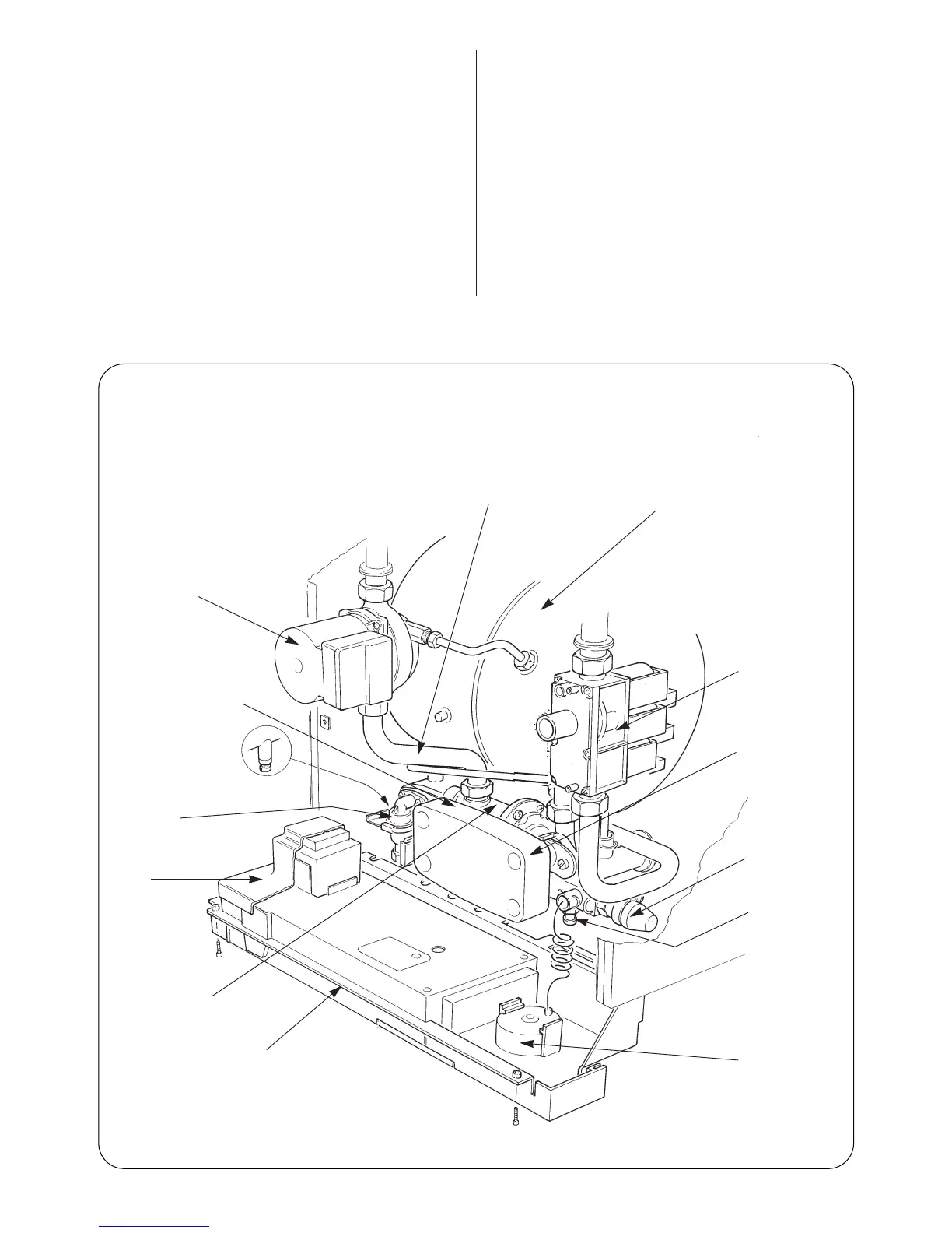
Fig. 28. Appliance Components (lower assembly)
Domestic hot water sen-
sor (not shown) located
behind water to water heat
exchanger
Circulating pump
Flow pipe from pump and
union connection
Expansion vessel
Gas valve
Water to water
heat exchanger
Pressure relief
valve
Drain tap
(C.H. Return)
Pressure Gauge
Facia and controls shown
in the service position
Plastic water
cover
Filling loop
Water diverting valve
and micro switch
assembly
Drain tap C.H. flow