223. Control Board. Refer to Fig. 35.
Check that the electricity supply to the appliance is turned off.
Remove the three screws fixing the facia bottom panel to the
facia. Remove the facia bottom panel. Retain the panel and
screws.
Carefully pull off all the connectors. Disconnect the mains supply
lead at terminal ST 12 and the earth connection at the back.
Pull off the three plastic control knobs. Take care not to damage
the knobs when pulling off.
Retain the knobs.
Hinge down the facia panel into the servicing position as
described in Section 15.3, c.
Remove the plastic water cover.
Remove the four corner screws on the back of the facia and sepa-
rate the metal back panel from the plastic facia.
Ease off the two spark electrode lead connections.
Release the plastic catch at each of the four mounting posts
pulling the control board forwards approximately 3mm to pre-
vent the plastic catch from returning.
Pull the board off the remainder of the mounting posts until it is
free.
Unplug the transformer from rear of the board. Discard the con-
trol board retain the transformer.
Plug in the transformer to the replacement control board. The
transformer will fit in one direction only.
Locate the replacement control board over the four mounting
posts and push back squarely until the plastic catch on the end
of each post clicks into place.
Reassemble in the reverse order and ensure:
i) the spark electrode leads are re-connected. Polarity is not
important.
ii) the connectors are fitted to the correct terminals.
Connectors are not interchangeable and will only fit the termi-
nals from which they were removed.
Reassemble the facia panel and facia bottom panel in the reverse
order. When replacing the control knobs ensure the knob with
the shortest shaft is fitted to the left hand control position.
.
23. Transformer. Refer to Fig. 35.
Check that the electricity supply to the appliance is turned off.
Remove the control board as described in Section 16.4, 23.
Pull the transformer from the back of the control board.
Fit the replacement transformer in the reverse order.
24
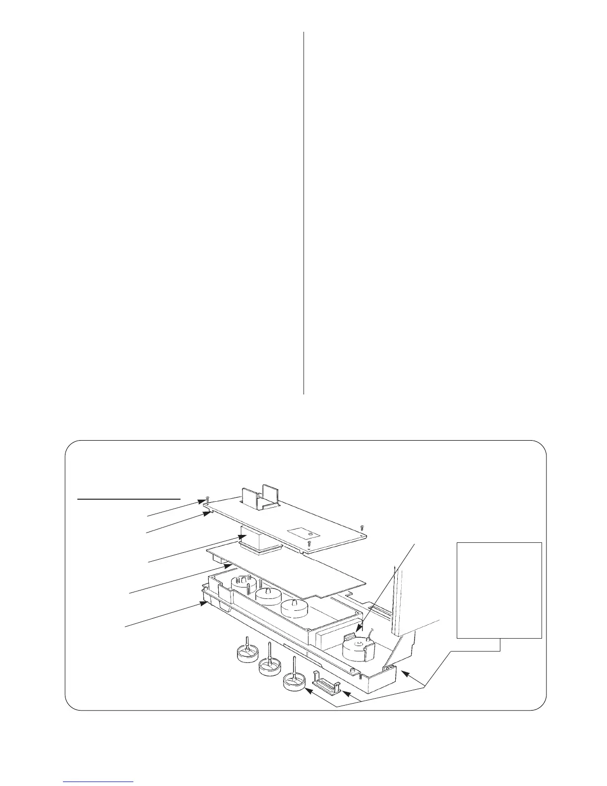
Fig. 35. Rear of Facia in Servicing Position, Control Board and Transformer.
Remove plastic water cover
Four fixing screws
Metal back panel
Plug in transformer
Control board
Plastic facia.
Lower into the Servicing
Position after removing two
fixing screws
Pressure gauge.
To remove ease plastic
clips apart
Before hinging facia
into the Servicing
Position remove:
Facia bottom panel
Pull off all connectors.
Disconnect mains
supply.
Pull off all plastic con-
trol knobs.