ONLY COMPONENTS SUPPLIED BY WORCESTER HEAT
SYSTEMS SHOULD BE USED.
ONLY COMPETENT PERSONNEL SHOULD ATTEMPT THE
CONVERSION.
CONVERSION FROM NATURAL GAS TO LPG SHOULD
NOT BE CARRIED OUT ON APPLIANCES INSTALLED IN
A ROOM OR INTERNAL SPACE BELOW GROUND LEVEL
Conversion Kit LPG to NG 7 716 192 307
Conversion Kit NG to LPG 7 716 192 308
1. Ensure the gas service cock is turned OFF and the electrical
supply is
ISOLATED.
2. Refer to the Servicing Instructions to remove the cabinet
front panel and inner casing.
3. Follow the dismantling instructions to remove the burner.
Refer to Section: Inspection and Servicing.
4. Remove the injector and replace with the relevant injector from
the kit. Refer to Section: Inspection and Servicing.
5. Remove the nut, end cap and bracket at the opposite end of the
burner. If the conversion is LPG to NG it is necessary to remove
the gauze. If the conversion is NG to LPG it is necessary to fit the
gauze supplied in the kit.
6. Refit the end cap ensuring that the support bracket is in the
correct orientation.
7. Remove the gas valve and replace with the gas valve
supplied in the kit. Refer to Section: Replacement of Parts.
8. Re-assemble the burner and inner casing.
9. Turn on the gas and electricity supplies and follow the
commissioning procedure to confirm gas soundness and
correct boiler operation.
10. Check and adjust the setting pressures to the values in the
table below and adjust if necessary. Refer also to the
Installation and Service Instructions Section: Replacement of
Parts "To Set the Burner Pressure".
11. Refit the plastic sealing cap to the gas valve modulating
valve adjuster and seal with a dab of paint or similar.
12. Turn off the boiler and when cool peel off the arrow from the
data plate on the combustion chamber front panel and re-
stick against the gas type for which the boiler has been
converted and adjusted.
13. Replace the boiler front panel.
The conversion is now complete.
39
20. Conversion Instructions
NOMINAL BOILER RATINGS
(10 minutes after lighting)
MAX. INPUT DHW kW 27.0 31.5 39.2 27.0 31.5 39.2
BURNER PRESSURE mbar 14.8 15.5 13.5 35.5 35.5 34.7
MAX. INPUT CH kW 27.0 27.0 30.1 27.0 27.0 30.1
BURNER PRESSURE mbar 14.8 10.8 8 35.3 24.3 21.3
MIN. INPUT DHW kW 11.4 11.4 11.9 11.4 11.4 11.9
BURNER PRESSURE mbar 1.5 1.0 0.9 5.4 3.8 3.1
BOILER ADJUSTED FOR
G20 (Natural Gas)
BOILER ADJUSTED FOR
G31 (Propane)
24CDi 28CDi
35CDi II
24CDi 28CDi
35CDi II
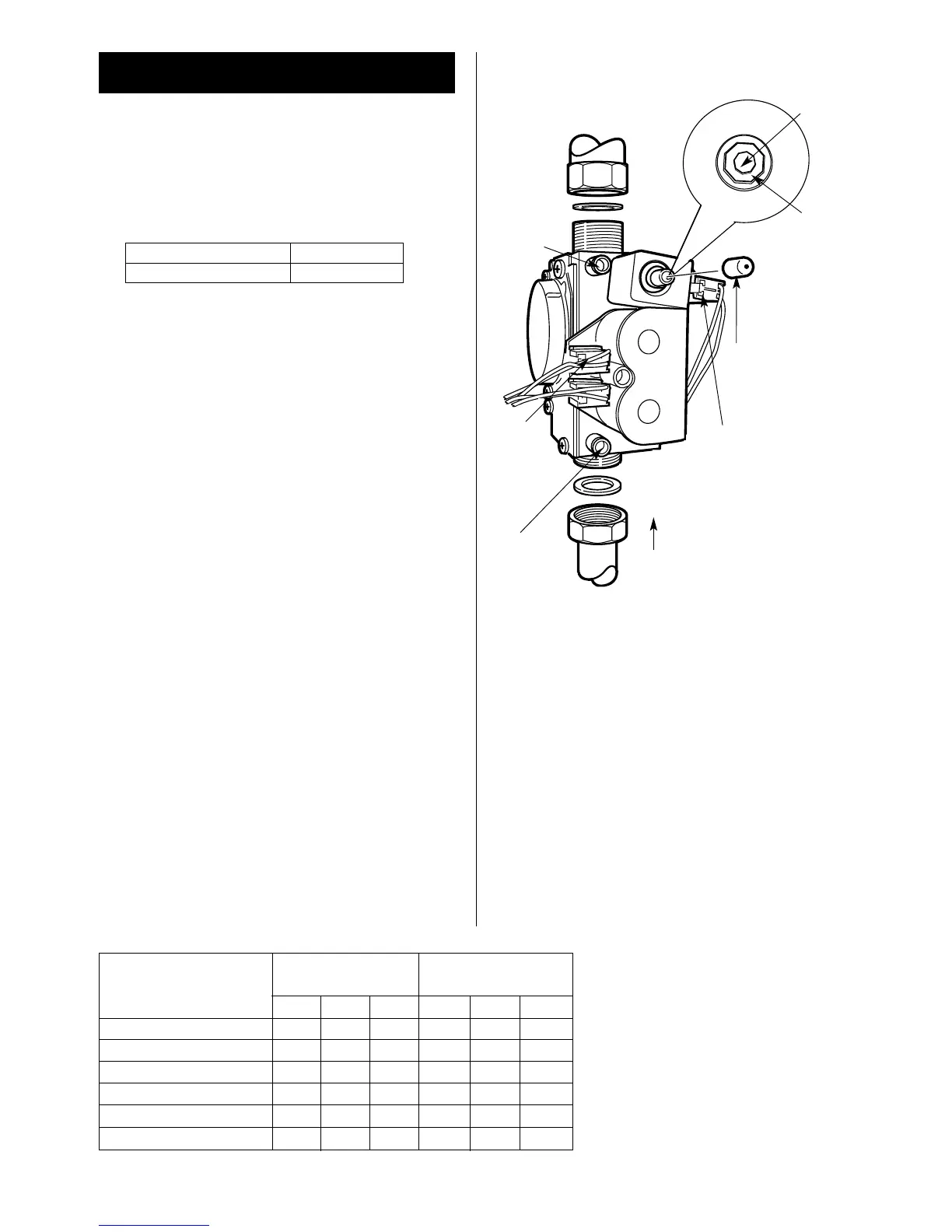
Max
2mm
Allen key
Min
3mm
Allen key
6
1
5
Minimum /
Maximum
pressure
adjuster -
Turn Allen key
Clockwise
to increase and
anti-clockwise
to decrease the
pressure.
3
2
GAS VALV E
4
1. Burner pressure test point
2. Main gas valve connections
3. Inlet pressure test point
4. Gas valve bracket
5. Electrical connections modulator (Blue:Blue)
6. Gas valve sealing cap

 Loading...