Neutral
19
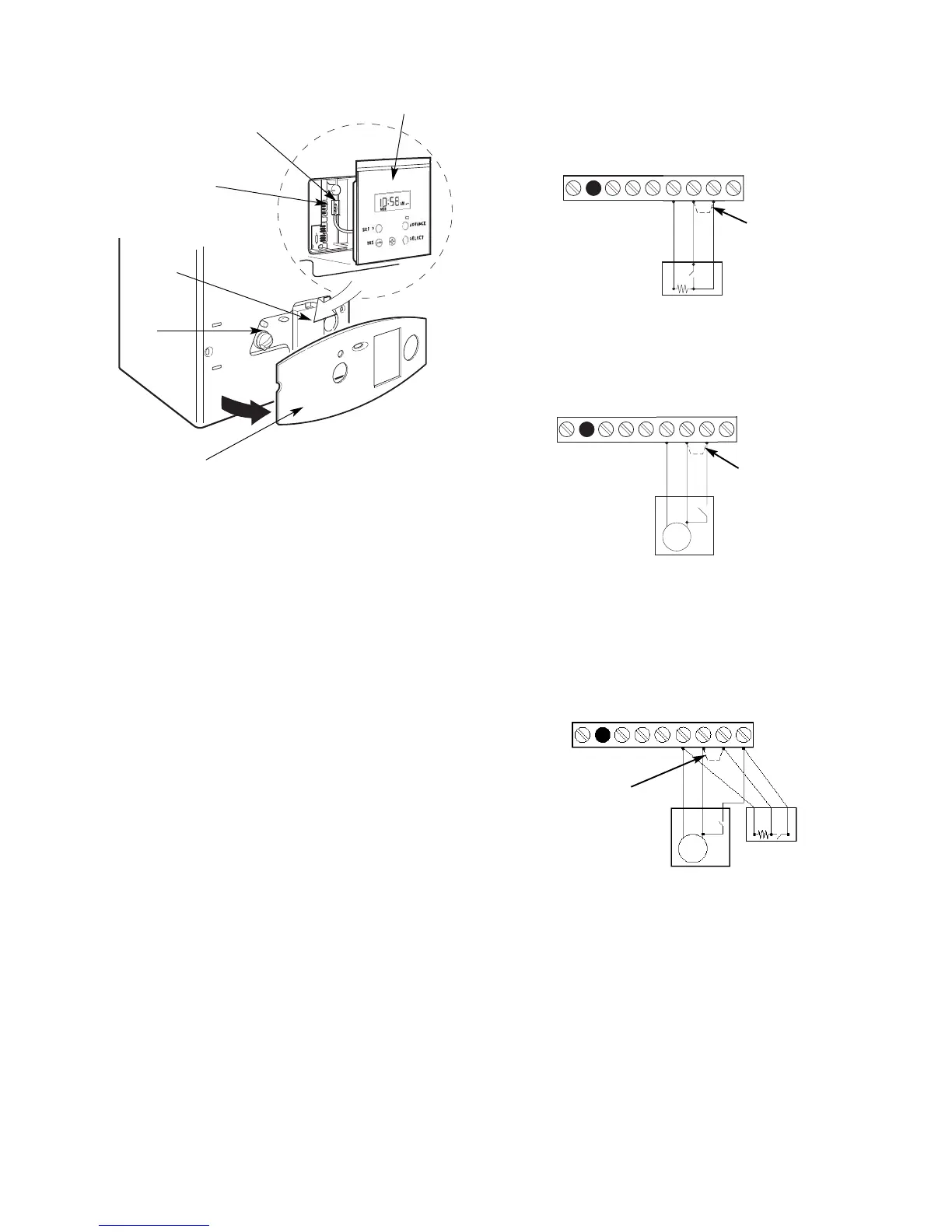
Fig 31 - Mains Voltage External Controls
Connections
230 V Room Thermostat Connections
Ns
Ls
L
R
ST2
Ns
Ls
L
R
ST2
Remove Link
Live
Switched Live
Neutral
Live
Switched Live
Motor
230 V Programmer Connections
230 V room thermostat and
Programmer Connections
Ns
Ls
LR
Neutral
Live
Neutral
Live
Switched Live
Motor
Remove Link
spare
spare
ST2
Remove Link
Fig. 30. Optional programmer connection
1. Facia (gently pull forward to un-clip and remove)
2. Control panel (boiler outer casing in place)
3. Programmer cover (un-clip to remove)
4. Programmer location in detail
5. Programmer connections
6. Programmer connector plug
7. Programmer
1
2
3
5
6
4
7