43
20. Conversion Instructions
NOMINAL BOILER RATINGS (10 Minutes After Lighting)
BOILER ADJUSTED FOR G20 (Natural Gas)
OUTPUT INPUT (Net) GAS RATE
kW kW m bar. m
3
/h
8.0 9.5 1.2 1.00
27.5 30.0 14.7 3.17
BOILER ADJUSTED FOR G31 (Propane)
8.0 9.5 3.4 0.39
27.5 30.0 35.3 1.23
Table 1. 28i
BURNER
PRESSURE
NOMINAL BOILER RATINGS (10 Minutes After Lighting)
BOILER ADJUSTED FOR G20 (Natural Gas)
OUTPUT INPUT (Net) GAS RATE
kW kW m bar. m
3
/h
3.5 9.5 1.4 1.00
23.5 25.9 13.6 2.74
BOILER ADJUSTED FOR G31 (Propane)
7.5 9.5 4.6 0.39
23.5 25.9 35.0 1.06
Table 1. 24i
BURNER
PRESSURE
Natural Gas: Net Input = Gross Input x 0.901 LPG (Propane): Net Input = Gross Input x 0.922
ONLY COMPONENTS SUPPLIED BY WORCESTER HEAT
SYSTEMS SHOULD BE USED
ONLY COMPETENT PERSONNEL SHOULD ATTEMPT THE
CONVERSION
CONVERSION FROM NATURAL GAS TO LPG SHOULD NOT BE
CARRIED OUT ON APPLIANCES INSTALLED IN A ROOM OR
INTERNAL SPACE BELOW GROUND LEVEL
1. Ensure the gas service cock is turned OFF and the electrical
supply is ISOLATED.
2. Refer to the Servicing Instrucions to remove the cabinet front
panel and inner casing.
3. Follow the dismantling instructions to remove the burner.
Refer to Installation and Service Instructions Section: Inspection
and Servicing.
4. Remove the injector and replace with the relevent injector
from the kit. Refer to Installation and Service Instructions
Section: Inspection and Servicing.
5. Remove the nut end cap and bracket at the opposite end of
the burner and insert the gauze from the kit for NG to LPG or
remove it for LPG to NG.
6. Refit the end cap ensuring that the support bracket is in the
correct orientation.
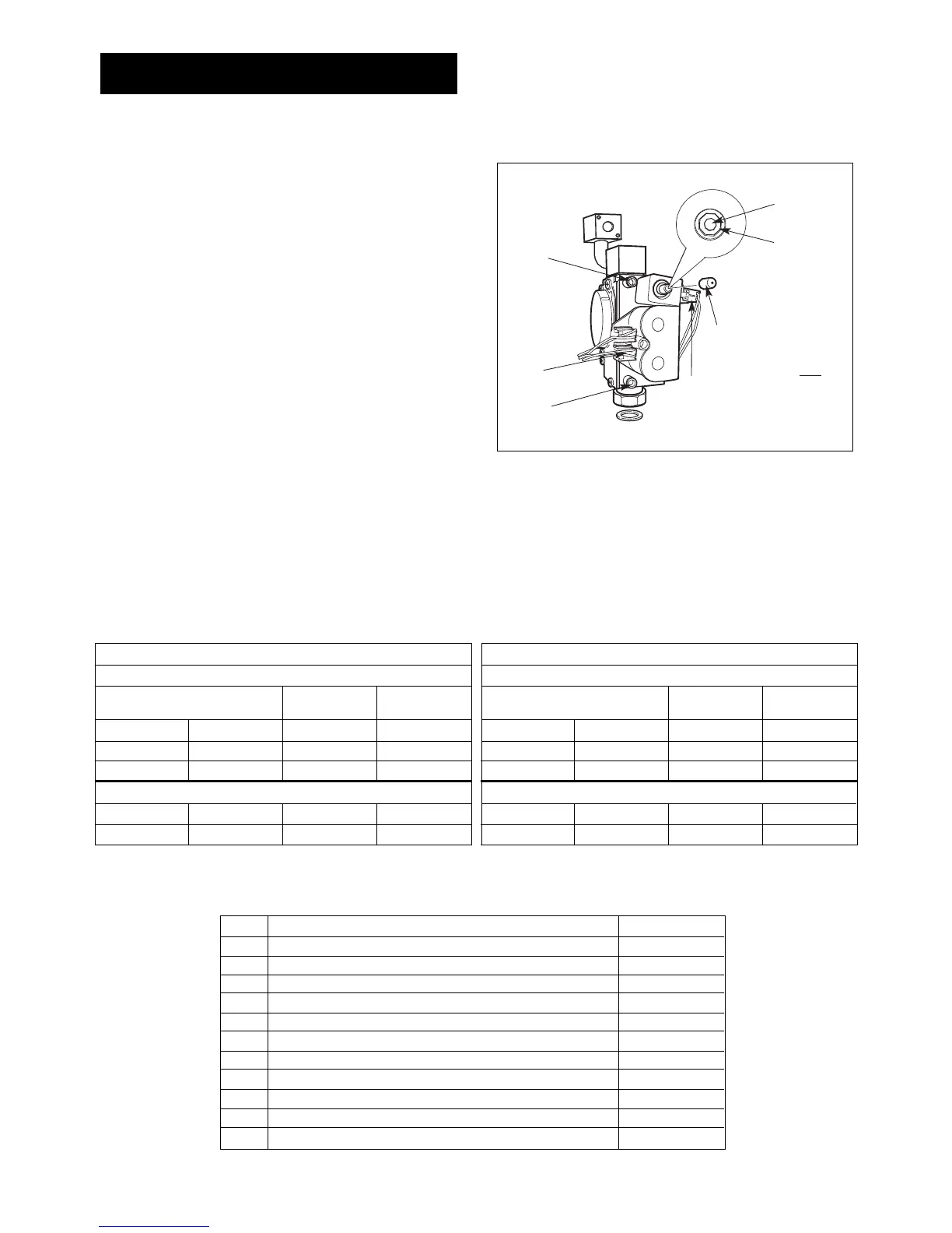
7. Remove the gas valve and replace with the gas valve
supplied in the kit. Refer to Installation and Service Instructions
Section: Replacement of Parts.
8. Re-assemble the burner and inner-casing.
9. Turn on the gas and electricity supplies and follow the
commissioning procedure to confirm gas soundness and correct
boiler operation.
10. Check and adjust the setting pressures to the values in the
table overleaf and adjust if necessary. Refer to Installation and
Service Instructions Section: Replacement of Parts. “To Set the
Burner Pressure”.
11. Refit the plastic sealing cap to the gas valve modulating
valve adjuster and seal with a dab of paint or similar.
12. Turn off the boiler and when cool peel off the arrow from the
data plate on the combustion chamber front panel and re-stick
against the gas type for which the boiler has been converted
and adjusted.
13. Replace the boiler front panel.
The conversion is now complete.
QTY DESCRIPTION PART No
1 Conversion Instructions
1 LPG Gas Valve Dungs BM771 sl 040 (for LPG to NG) 8 716 105 654
1 NG Gas Valve Dungs BM771 sl 040 (for NG to LPG) 8 716 105 650
1 Burner gauze 8 716 142 601
1 Fibre washer 8 710 103 043
2 O rings 8 716 140 827
1 Injector 2.7mm 24i LPG 8 716 156 373
1 Injector 2.78mm 28i LPG 8 716 140 209
1 Injector 4.3mm 24i NG 8 716 105 033
1 Injector 4.5mm 28i NG 8 716 140 208
1 Copper washer 8 716 101 994