Inner Case Cover Unscrew the two screws and lift off. Refer to Fig. 39.
Combustion Chamber Cover Unscrew the two screws, lift and
pull forward to remove. Refer to Fig. 41.
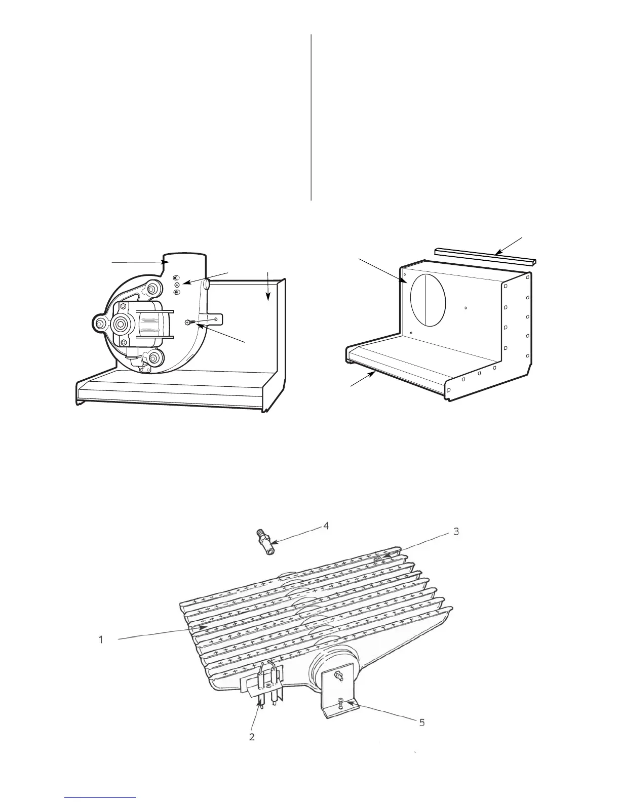
Fan Carefully pull off the electrical connections and the
tubes from the airflow-sensing device. Unscrew the
three screws and remove the fan assembly. Refer to Fig.
42.
Flue Hood Remove the fan. Slide out the hood. Ensure the rear
seal is in good condition and secure before replacing
the flue hood. Refer to Fig. 43.
Burner Remove the combustion chamber. Carefully pull-off
the connections to the spark electrodes and
disconnect the flame sense electrode lead. Unscrew
the support bracket and withdraw the burner
assembly. Refer to Fig. 44.
15.5 Component Cleaning
Only use a non-metallic brush to clean components.
Do not use a metal probe to clean the injector.
Clean the fan taking care not to block air flow sensor.
Clean the burner to ensure that the blades are clear.
Clean the electrodes, replace if there is any sign of deterioration.
Clean the heat exchanger. Cover the burner injector. Remove
any deposits from the heat exchanger from the top and bottom.
Carefully straighten any distorted fins on the heat exchanger.
Check the combustion chamber insulation and replace if there is
any sign of damage or deterioration. Refer to Section 16.5.
Clean the controls in-situ.
Check that all screws are tight and the connections properly
remade with the appropriate gaskets/O-rings/seals.
Re-commission, as necessary, for correct operation to the users
requirements. Refer to Section 13 Commissioning.
24
Fig. 42. Fan assembly
Fig. 43. Flue hood
Fig. 44. Burner assembly
1
2
3
1. Flue hood
2. Rear sealing strip (on back panel)
3. Combustion chamber cover locating channel
1
2 3
4
1. Fan assembly
2. Flow sensor
3. Flue hood
4. Fan fixing screws (3)
1. Burner assembly
2. Spark electrode assembly
3. Flame sense electrode
4. Injector
5. Support bracket fixing screw