5 Combustion Chamber Insulation.
Remove inner casing door and combustion chamber cover.
Slide the damaged insulation panel from the appliance
Rear
Remove heat exchanger. Refer to Fig 61.
Remove the side insulation panels.
Slide the rear insulation forward and up to remove.
Replacement is the reverse of removal. Refer to Fig 50.
6 Pressure Gauge
Remove the clip-on facia cover, cabinet, unscrew the single screw
and lower the facia panel onto the lower support lugs. Refer to
Fig. 39 and 40. Check that the appliance has been fully drained.
Slide the captive clip upwards and remove the pressure-sensing
head. Refer to Fig. 52.
Unclip the gauge head from its mounting bracket and remove.
Refer to Fig. 51.
Check the condition of the O-ring at the pressure capillary head
before fitting the replacement gauge.
7 Relief Valve
Remove the clip-on facia cover, cabinet, unscrew the single screw
and lower the facia onto the lower support lugs.
Check that the appliance has been fully drained.
Disconnect the relief valve discharge pipe .
Pull down the fixing clip and pull out the relief valve. Refer to Fig. 17.
NOTE: The clip does not need to be fully removed.
8 Flow Turbine/ Filter/ Restrictor
Drain the DHW circuit as described at the start of Section 16.
Remove the clip-on facia cover, cabinet, unscrew the single screw
and lower the facia panel onto the lower support lugs.
Separate the turbine in-line electrical connector.
Remove the two fixing clips and withdraw the turbine assembly.
27
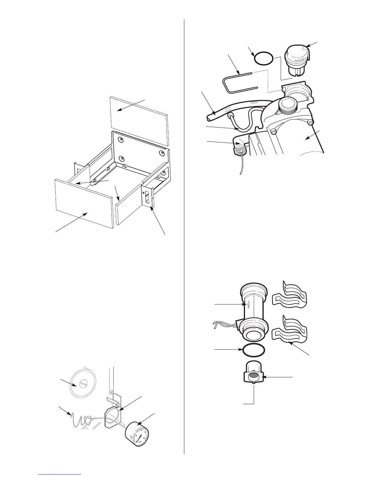
Fig. 51. Pressure Gauge head
Fig. 52. Pressure Gauge connection.
Fig. 50. Combustion Chamber Insulation.
2
3
1
1. Combustion chamber assembly
2. Rear insulation panel
3. Side insulation panel
4. Front insulation panel (fixed to combustion chamber
front cover)
1
2
4
3
1. Pump
2. Pressure gauge capillary
3. Pressure gauge head
4. Mounting bracket
1
5
2
3
1. Pump
2. Pressure gauge connection
3. System connection hose
4. Air vent fixing clip
5. Air vent cartridge
6. By-pass pipe
7. 0-Ring
Fig. 54. Water flow turbine.
2
3
1
1. Flow turbine
2. Clips (2)
3. O-ring
4. Filter/Flow restrictor
4
4
6
7
24i White 8 l/min
28i Blue 10 l/min
4