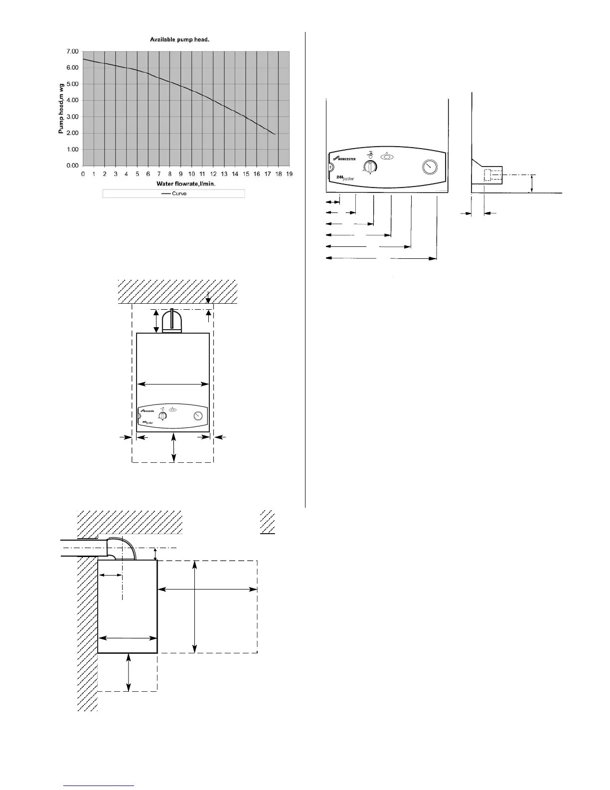
Fig. 4. Appliance casing dimensions and
required clearances (side view).
All dimensions in mm
24i 28i
A CH Flow = 70 90
B Relief Valve Discharge = 88 108
C DHW Outlet = 135 155
D Gas = 200 220
E Cold Water Inlet = 265 285
F CH Return = 330 350
Fig. 3. Appliance casing dimensions and
required clearances for installation/servicing
All dimensions in mm
30
158
10
10
7
B
C
D
E
130
24i = 400
102
600
600
203
325
200
200
F
All dimensions in mm
28i = 440
A
Fig. 5. Pipework connections
Unventilated Compartment — for clearances refer to Table 8
Unventilated Compartment — Refer to Table 8
Dimensions
A,B,E,F
18
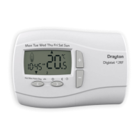
Minimum system flow rate
Please ensure that the external system flow rate returning to the
appliance is greater than 2 litres/minute.