Do you have a question about the Worcester 28CDi RSF and is the answer not in the manual?
| Model | 28CDi RSF |
|---|---|
| Category | Boiler |
| Output | 28 kW |
| Fuel Type | Natural Gas |
| Efficiency Rating | A |
| Mounting | Wall-mounted |
| Max. Central Heating Output | 24 kW |
| Max. DHW Output | 28 kW |
| Efficiency | 90% |
| Hot Water Flow Rate | 11.4 L/min |
| Max Working Pressure | 3 bar |
Ensure installation adheres to Gas Safety (Installation and Use) Regulations.
Manufacturer's instructions do not override statutory obligations.
Installation must comply with relevant British Standards and building regulations.
Installation should meet other relevant British Standards for optimal performance.
Contact manufacturer for specific installation advice when needed.
The appliance is not suitable for external installation.
Appliance controls set for maximum output of 28 kW (DHW) and 24 kW (CH).
Features direct burner ignition; no pilot light is used.
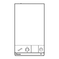
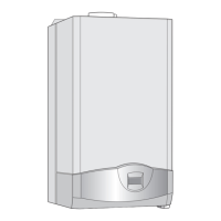
Overview of key components like heat exchangers, controls, and vessel.
Specifies mains supply voltage, frequency, and fuse ratings.
Check data plate for correct gas supply (Natural Gas or Propane).
Appliance and flue components are packed separately.
Appliance for sealed/open vent systems, ventilation, clearances.
Details on flue type, lengths, and terminal guard.
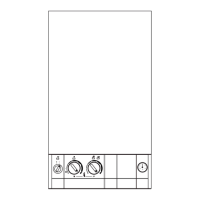
Modulating controls, ON/OFF switch, temperature controls, programmer options.
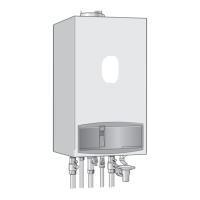
Flushing, pipework, pressure, drain cock, relief valve discharge.
Requirements for water fixtures and flow balancing.
Do not operate without water, with cover removed, or without power off.
How the appliance operates for DHW and Central Heating.
Boiler output and input ratings for Natural Gas and Propane.
Specifications for flue wall hole diameter and lengths.
Pump head, flow rate, and temperature rise for different boiler outputs.
Details on fittings, dimensions, weight, pressure, and temperature.
Room installation, electrical safety near baths/showers.
No special wall protection needed; wall must support appliance weight.
Required clearances for installation and servicing are detailed.
Guidelines for fitting in a clothes cupboard, adhering to standards.
Compartment requirements, including no vents if clearances are met.
Minimum distance from combustible surfaces to appliance casing.
Minimum distance between cupboard door and cabinet front.
LPG installation prohibition in rooms below ground level.
Flue installation must comply with BS 5440:Part 1.
Avoid obstructions and nuisance from discharge.
Install aluminum shield if terminal is near plastic gutters/eaves.
Guards are required for terminals less than 2m above accessible surfaces.
Avoid siting where terminal steam could cause a nuisance.
Prevent combustion products from entering ventilated roof voids.
Appliance does not require a separate vent for combustion air.
Clearances for cupboard installation without vents.
Ventilation openings for cooling in compartments with reduced clearances.
Specifies minimum free areas for air vents based on location.
Systems must comply with BS 6798 and BS 5449.
Appliance must not operate without a full, vented, and pressurized system.
PRV operates at 3 bar; discharge must be safe.
Pressure gauge indicates system pressure that must be maintained.
10-litre expansion vessel for static head of 5 metres.
Accommodates ~83 litres; charge pressure can be increased.
Appliance includes a system filling link for adding water.
Water loss from the system must be replaced.
Step-by-step guide to filling the system using the filling key.
Repeated venting loses water; pressure must be maintained.
Mains water connections require local Water Company authority.
The pump is set at maximum and must not be adjusted.
System connections must withstand up to 3 bar pressure.
Radiator valves must conform to BS 2767:10.
Other valves used should conform to BS 1010.
Pipework sizing based on Section 3, Table 4.
Cistern arrangement for minimum static head requirement.
Feed and vent pipe diameter and continuous rise requirement.
A pressure relief valve is not required on an open vented system.
Air expelled via feed/vent or dissipated into the system.
The pump is set to maximum and must not be reset.
Requirements for DHW operation before central heating connection.
General requirements for DHW system, consult local water company.
Requirements for cold water inlet and expansion vessel connection.
Final 600mm of cold water connection must be copper.
Appliance suitable for mains pressure up to 10 bar.
Appliance is fitted with a mains supply isolating valve.
Specifies the maximum domestic hot water flow rate.
Reduced flow rate may be needed in winter for desired temperature.
Suggests insulating long pipe runs to prevent rapid cooling.
Taps and mixing valves must suit mains pressure and temperature.
Thermostatic or pressure equalising shower valves recommended.
Shower head position to prevent immersion in bath water.
Requirements for direct supply to bidets, including shrouded outlets.
Scale accumulation is unlikely; treatment optional if needed.
Details on voltage, frequency, power consumption, and fuses.
Requirement for complete isolation of the appliance.
Acceptable methods for connecting mains electricity supply.
The appliance must be properly earthed.
Details on the type and size of the mains cable.
Wiring must comply with IEE Regulations and local rules.
Wiring for room thermostats and external programmers.
Information on optional facia-mounted programmer kits.
Option to fit a time switch or programmer externally.
Boiler has an internal frost thermostat for protection.
Checks for short circuits, polarity, earth continuity, resistance.
Details on standard and extension flue lengths and bends.
Instructions for fixing the wall mounting plate.
Steps for securing the appliance to the wall mounting plate.
Procedure for fixing the flue turret and automatic air vent.
Checks for appliance components and wall plate assembly.
Instructions for preparing and assembling air and flue ducts.
Steps for fitting the duct assembly externally to the appliance.
Instructions for fitting the duct assembly internally.
Guidance on fitting flue bends and calculating equivalent lengths.
Final checks on connections, electrical supply, and system pressure.
Overview of appliance settings and system checks before commissioning.
Steps to prepare the appliance and system for commissioning.
Procedure to test the pressure relief valve operation.
Setting the correct charge pressure for the expansion vessel.
Filling the system and setting the initial system pressure.
Setting up any fitted programmer according to its instructions.
Procedures for setting burner pressure for different modes.
Checks for ignition and operation during hot water demand.
Checks for heating output, radiator heating, and system balancing.
Testing combined operation and hot water priority.
Final checks, tightening screws, gas soundness, and user handover.
Instruct the user on appliance operation and provide leaflet.
Advise the user on actions if the heating system is unused in frost.
Inform the user about the sealed system's set pressure.
Emphasize the need for regular servicing and maintenance contracts.
Set the system controls according to the user's specific requirements.
Suggest settings for external programmers for domestic hot water.
Appliance requires checking and servicing at regular intervals, ideally annually.
Checks for flue terminal, compartment vents, and system leaks.
Steps for measuring flue gases under constant output conditions.
Steps to dismantle the appliance for component access.
Cleaning procedures for the fan, burner, heat exchanger, and insulation.
Testing gas soundness and appliance operation after servicing.
Switch off supplies, check soundness and function after replacement.
Information on accessing components for replacement.
Steps for draining the central heating and DHW circuits.
Procedures for replacing specific components like the automatic air vent.
Steps to replace the air flow pressure switch.
Procedure for removing and replacing the fan assembly.
Steps to replace the overheat thermostat.
Procedure for replacing the gas to water heat exchanger.
Replacing fibre insulation pads in the combustion chamber.
Steps for replacing the burner assembly.
Procedure for replacing the burner injector.
Steps to replace the spark electrode assembly and set the gap.
Procedure for replacing the flame sensor and setting the gap.
Replacing the gas valve and setting burner pressures.
Steps to replace the central heating sensor.
Steps to replace the domestic hot water sensor.
Procedure for replacing the circulating pump.
Steps to replace the expansion vessel.
Procedure for replacing the pressure relief valve.
Replacing the micro switch assembly on the water diverting valve.
Steps to replace the water diverting valve.
Procedure for replacing the water to water heat exchanger.
Steps to replace the domestic hot water flow restrictor.
Procedure for replacing the pressure gauge.
Steps to replace the control board.
Procedure for replacing the filling loop assembly.
Steps to replace the transformer.
Illustrates the sequence of operations for central heating.
Illustrates the sequence of operations for domestic hot water.
Illustrates the sequence of operations for the overrun function.
Illustrates the sequence of operations for the autofrost function.
Overview of light patterns indicating faults.
Troubleshooting steps when no lights are displayed.
Troubleshooting steps when only green light works.
Troubleshooting steps when red lights work but no green.
Troubleshooting steps when one light is out.
Troubleshooting steps for constant light indication.
Troubleshooting steps for two lights flashing slowly.
Troubleshooting steps for slow flashing lights.
Troubleshooting steps for fast flashing lights.
Troubleshooting steps for specific flashing patterns.
Troubleshooting steps for sequence-dependent flashing faults.
Troubleshooting for faults not covered by specific light patterns.
Essential electrical checks before and after fault finding.
Diagnostic flowchart for Fail Point A.
Diagnostic flowchart for Fail Point B.
Diagnostic flowchart for Fail Point C.
Diagnostic flowchart for Fail Point D.
Diagnostic flowchart for Fail Point E.
Diagnostic flowchart for Fail Point F.
Diagnostic flowchart for primary overheat faults.
Diagnostic flowchart for burner lockout faults.
Diagnostic flowchart for sensor faults.
Diagnostic flowchart for air pressure faults.
Diagnostic flowchart for other or unspecified faults.