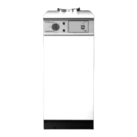
3
3. Technical Data
re-setting the speed control knob. This is located on the pump
electrical connection block. Three pump speeds are available,
number 1 being the lowest.
Expansion Vessel
A 10 litre expansion vessel is included within the appliance
cabinet.
Pressure Gauge
A 4 bar pressure gauge is included to allow the system pressure
to be checked and set to the correct level.
Pressure Relief Valve
A 3 bar relief valve is fitted to protect the appliance during
dangerous over-pressure conditions.
Manual Reset Thermostat
An overheat thermostat is located on the underside of the
electrical control box and is accessible by removing the cabinet
front panel.
If a boiler overheat condition arises, the burner will remain
inoperative until the thermostat button is reset.
2.8 Operation
The appliance is supplied with a facia mounted operating switch
to allow the selection of hot water only in the upper position or
central heating and hot water in the lower position.
Domestic Hot Water Mode
The appliance primary hot water is used to heat a domestic hot
water cylinder. The water may be transported to the cylinder by
natural gravity circulation or by a fully pumped method. Control
of the system will depend on which method is used and reference
should be made to the control system manufacturers instructions.
Off
The heating system will remain off unless there is a demand via
the frost thermostat ( where fitted ) whereby the frost thermostat
will activate the pump and burner until the demand is satisfied.
The burner will remain inoperative in all other circumstances.
Central Heating and Hot Water Mode
The appliance will supply heat to the central heating system as
required. The water supplied to the central heating circuit can be
set to the desired temperature by adjusting the heating control
thermostat located on the facia panel.
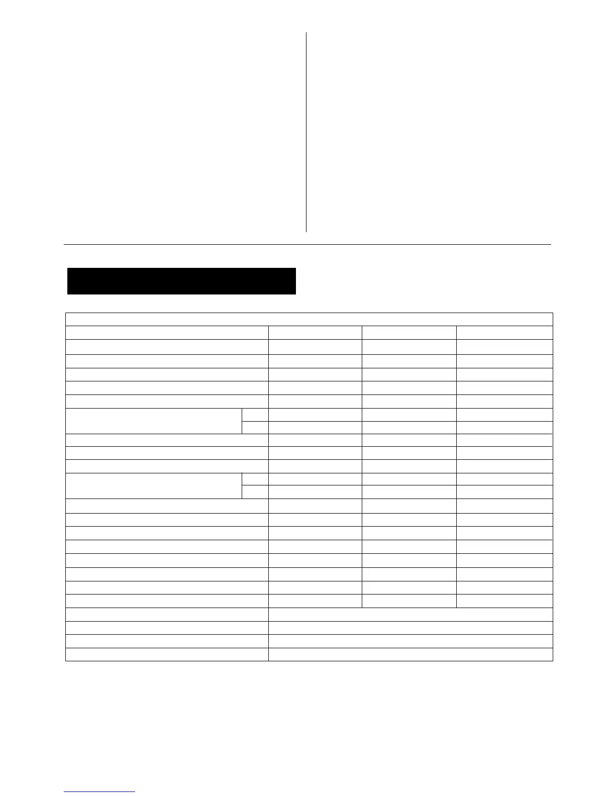
SPECIFICATIONS
Model 12/14 15/19 20/25
POWER SUPPLY 230V 50 Hz 230V 50 Hz 230V 50 Hz
IP RATING IP 20 IP20 IP 20
HEATING FLOW 22mm 22mm 22mm
HEATING RETURN 1 in. BSP 1 in. BSP 1 in. BSP
FUEL LINE 10 mm Compression 10 mm Compression 10 mm Compression
FLUE REQUIREMENT
CF 100 mm (4 in.) 100 mm (4 in.) 100 mm (4 in.)
RS Balanced Flue Kit (Sec. 7.3) Balanced Flue Kit (Sec. 7.3) Balanced Flue Kit (Sec. 7.3)
HEARTH TEMPERATURE Below 100°C Below 100°C Below 100°C
MAXIMUM STATIC HEAD 30 m (98 ft.) 30 m (98 ft.) 30 m (98 ft.)
PRIMARY WATER CAPACITY 20 litres (4.4 gal.) 20 litres (4.4 gal.) 23.5 litres (5.2 gal.)
WEIGHT
CF 102Kg (224 lbs.) 105Kg (231 lbs.) 116Kg (255 lbs)
RS 106Kg (234 lbs.) 109Kg (240 lbs.) 121Kg (267 lbs)
HEIGHT 855 mm (33.7 in.) 855 mm (33.7 in.) 855 mm (33.7 in.)
WIDTH 370 mm (14.6 in.) 370 mm (14.6 in.) 370 mm (14.6 in.)
DEPTH 600 mm (23.6 in.) 600 mm (23.6 in.) 600 mm (23.6 in.)
BURNER Electro Oil Inter B9 A Electro Oil Inter B9 B Electro Oil Inter B11C
WATER SIDE RESISTANCE 10°C Difference 7 mbar 8 mbar 18 mbar
WATER SIDE RESISTANCE 20°C Difference 3 mbar 6 mbar 12 mbar
EXIT FLUE GAS MASS FLOW 24Kg/hr 35Kg/hr 43Kg/hr
SEDBUK RATING* ( SEDBUK BAND C ) 85.3% 85.5% 85.3%
CONTROL THERMOSTAT RANGE 55°C minimum Cut In to 82°C maximum Cut Out
CONTROL THERMOSTAT DIFFERENTIAL 5°C
HIGH LIMIT THERMOSTAT BREAK POINT 100 + 0/–6°C
MANUAL RESET THERMOSTAT BREAK POINT 110 +0/–6°C
Table 1
* The value is used in the UK Government Standard Assesment Procedure (SAP) for energy ratings for dwellings.