* NOTE: For use on conventional flue only.
** NOTE: The flue gas temperature is measured in the gas sampling hole on the flue outlet plate. The probe should be inserted to a depth of 50mm and angled towards the flue outlet.
The temperature measured is not an absolute flue gas temperature and is for general guidance purposes only!
NOTE: The pump pressure given is for general guidance only as variations in nozzle output can be up to ± 15%. It is, therefore, essential that the air is adjusted to give the correct CO
2
value.
NOTE: The nozzle type used on 28 Sec. Kerosene outputs are nozzles calibrated specifically for use with 28 Sec. Kerosene which gives less variation in nozzle output than the standard 35
Sec. Gas Oil nozzles. However, if a 28 Sec. Kerosene nozzle is not available at servicing or commissioning it is appropriate to install a 35 Sec. Gas Oil nozzle providing the output, spray
angle and pattern of the nozzle is the same as the 28 Sec. Kerosene nozzle (e.g. 0.75 80°EH may be replaced with a 0.75.80°H).
28 Sec. Kerosene 0.40 60°ES 130 1.11 1.41 180 10.0 6.0 13.5 46,000 12 41,000
28 Sec. Kerosene 0.50 60°ES 100 1.30 1.64 195 11.5 7.0 15.5 53,000 14 48,000
NOMINAL BOILER RATING AT NORMAL OPERATING TEMPERATURE
12/14 Table 2. Electro Oil Inter B9A Burner (See Fig. 21)
Fuel Nozzle
Pump
Pressure
(p.s.i.)
Fuel Flow
Rate
Flue Gas
Temp.
(°C)**
%CO
2
Approx.
Air
Setting
Appliance
Input
kW Btu/hr kW Btu/hr
Output
Kg/h l/h
28 Sec. Kerosene 0.50 60°ES 110 1.40 1.77 215 10.5 8.5 17 58,000 15 51,000
28 Sec. Kerosene 0.55 80°EH 115 1.59 2.01 225 10.5 8.75 19 65,000 17 58,000
28 Sec. Kerosene 0.60 60°ES 105 1.78 2.25 235 11.5 9.0 21.5 73,000 19 65,000
35 Sec. Gas Oil* 0.50 80°S 155 1.80 2.12 235 11.5 9.0 21.5 73,000 19 65,000
NOMINAL BOILER RATING AT NORMAL OPERATING TEMPERATURE
15/19 Table 3. Electro Oil Inter B9B Burner (See Fig. 22)
Fuel Nozzle
Pump
Pressure
(p.s.i.)
Fuel Flow
Rate
Flue Gas
Temp.
(°C)**
%CO
2
Approx.
Air
Setting
Appliance
Input
kW Btu/hr kW Btu/hr
Output
Kg/h l/h
28 Sec. Kerosene 0.60 80°EH 130 1.87 2.37 190 11.0-11.5 5.5 22.5 77,000 20 68,000
28 Sec. Kerosene 0.75 80°EH 105 2.10 2.66 205 11.5-12.0 6.0 25 86,000 22.5 77,000
28 Sec. Kerosene 0.75 80°EH 130 2.34 2.96 220 12.0-12.5 6.5 28 96,000 25 85,000
35 Sec. Gas Oil* 0.60 80°S 120 2.13 2.51 205 11.5-12.0 6.0 25 86,000 22.5 77,000
35 Sec. Gas Oil* 0.60 80°S 150 2.37 2.79 220 12.0-12.5 6.5 28 96,000 25 85,000
NOMINAL BOILER RATING AT NORMAL OPERATING TEMPERATURE
20/25 Table 4. Electro Oil Inter B11C Burner (See Fig. 23)
Fuel Nozzle
Pump
Pressure
(p.s.i.)
Fuel Flow
Rate
Flue Gas
Temp.
(°C)**
%CO
2
Approx.
Air
Setting
Appliance
Input
kW Btu/hr kW Btu/hr
Output
Kg/h l/h
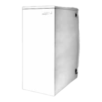
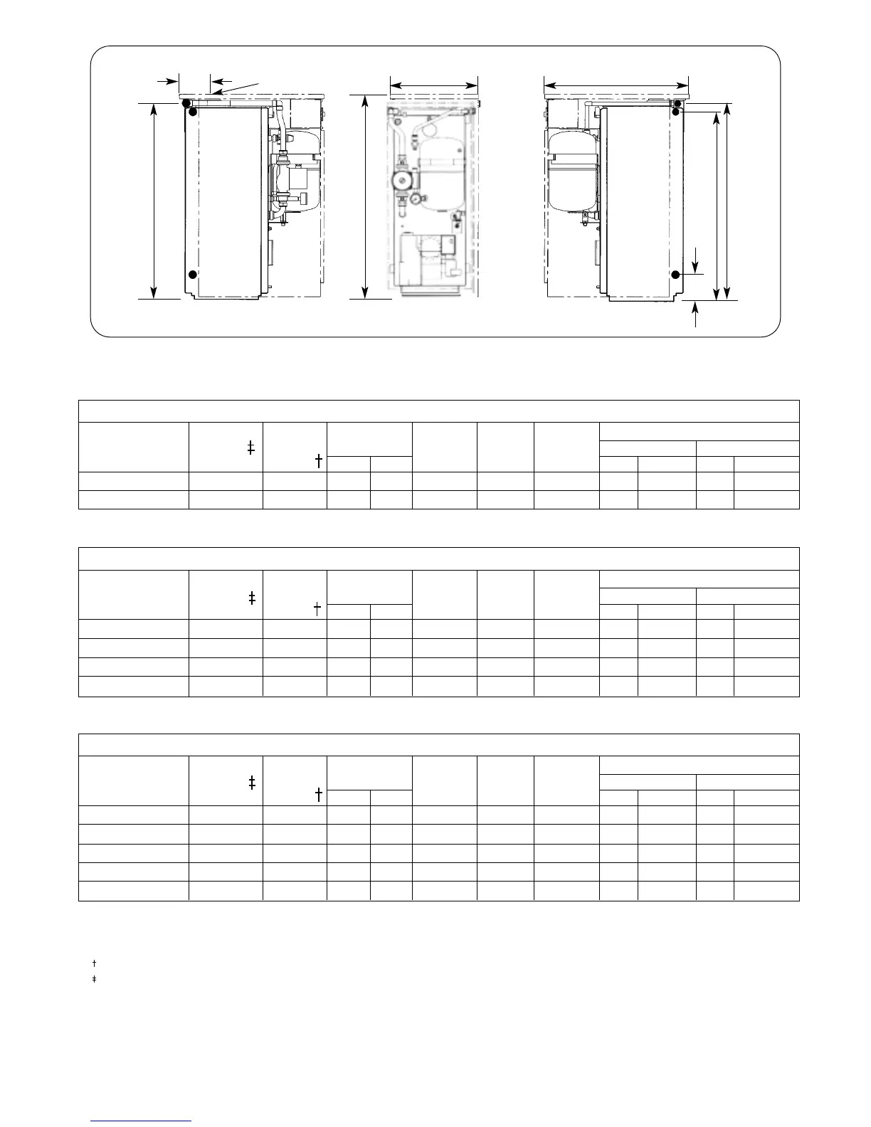
Fig. 1. Cabinet and Pipework Dimensions
1
2
4
3
2
816 mm
814 mm
780 mm
110 mm
600 mm
41
370 mm
855 mm
1. Central heating flow (22mm compression). 2. Central heating return (1" BSP).
3. Gravity feed flow/optional air vent point (1" BSP). 4. Pressure relief discharge pipe (15mm compression).
92mm
Flue Center