Pre-Installation
Greenstar Danesmoor Utility
ErP
and Utility System
ErP
- 6 720 813 286 (2014/09) 19
Maintenance clearances
Figure 24 shows the clearances required for maintenance.
Fig. 24 Maintenance and repair clearances
Minimum air vent area (cm
3
) for appliances installed in
compartments
Compartments
Follow the requirements of BS 5410 and note:
• Minimum clearances must be maintained.
• An access door is required to install, service and maintain the boiler
and any ancillary equipment.
• If fitting the boiler into an airing cupboard use a non-combustible
material (if perforated, maximum hole sizes of 13mm) to separate the
boiler from the airing space.
Venting compartments
There must be sufficient clearance around the appliance to allow proper
circulation of ventilation air. The clearances required for installation and
servicing will normally be adequate for ventilation.
• Ventilation must be provided for boilers fitted into compartments as
described in BS 5410.
• Combustion air must not be taken from a room or internal space
containing a bath or shower and must not communicate with a protected
area such as a hall, stairway, landing, corridor, lobby, shaft etc.
• Air vents must allow access for clean free air and must be sited to
comply with the flue terminal position requirements.
• Air ducting runs must not exceed 3m.
• Low level air vents must be less than 450mm from the floor.
• A warning label must be added to the vents with a statement to the
effect: ''Do not block this vent. Do not use for storage.”
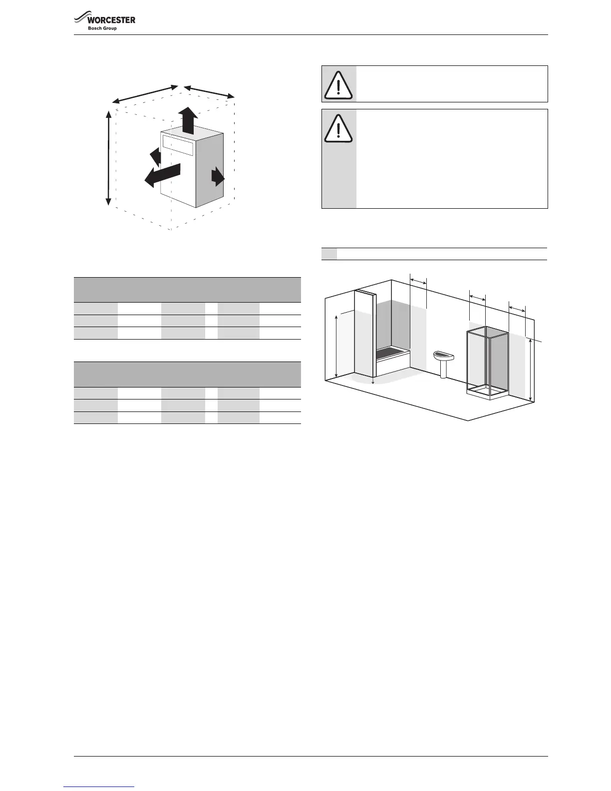
Showers/bathrooms
The boiler must not be installed in the bath or shower or in zones 1 or 2
(the shaded areas shown on the diagrams opposite).
The boiler can be installed outside the shaded areas.
Fig. 25 Bathroom zones
4.8 Flue terminal positions
Flue terminals must be positioned to avoid combustion products
entering into buildings.
The flue must be fitted and terminated in accordance with the
recommendations of BS5410.
The flue must not cause an obstruction.
Discharge from the flue outlet must not be a nuisance.
Flue gases have a tendency to plume and in certain weather conditions a
white plume of condensation will be discharged from the flue outlet
which could be regarded as a nuisance, for example, near security
lighting.
There should be no restriction preventing the clearance of combustion
products from the terminal.
The air inlet/outlet duct and the terminal of the boiler must not be closer
than 25mm to any combustible material. Detailed recommendations on
protection of combustible materials are given in BS 5410:1
A protective stainless steel terminal guard, must be fitted if the terminal
is 2m or less above a surface where people have access.
See 'Contact Information' on the back cover for flue guard information.
The following additional guidelines (from part L Exceptions Guidance
Document) are recommended when determining the flue outlet
position:
Avoid discharging flue gases into car ports or narrow passageways.
Model
Internal ventilation External ventilation
High level Low level High level Low level
12/18 198 297 99 198
18/25 275 413 138 275
25/32 330 495 165 330
Table 5 Conventional flue
Model
Internal ventilation External ventilation
High level Low level High level Low level
12/18 198 198 99 99
18/25 275 275 138 138
25/32 330 330 165 165
Table 6 Room sealed flue
 Loading...