Pre-Installation
Greenstar Heatslave II External
ErP -
6 720 813 345 (2014/09)16
4.8 Flue options
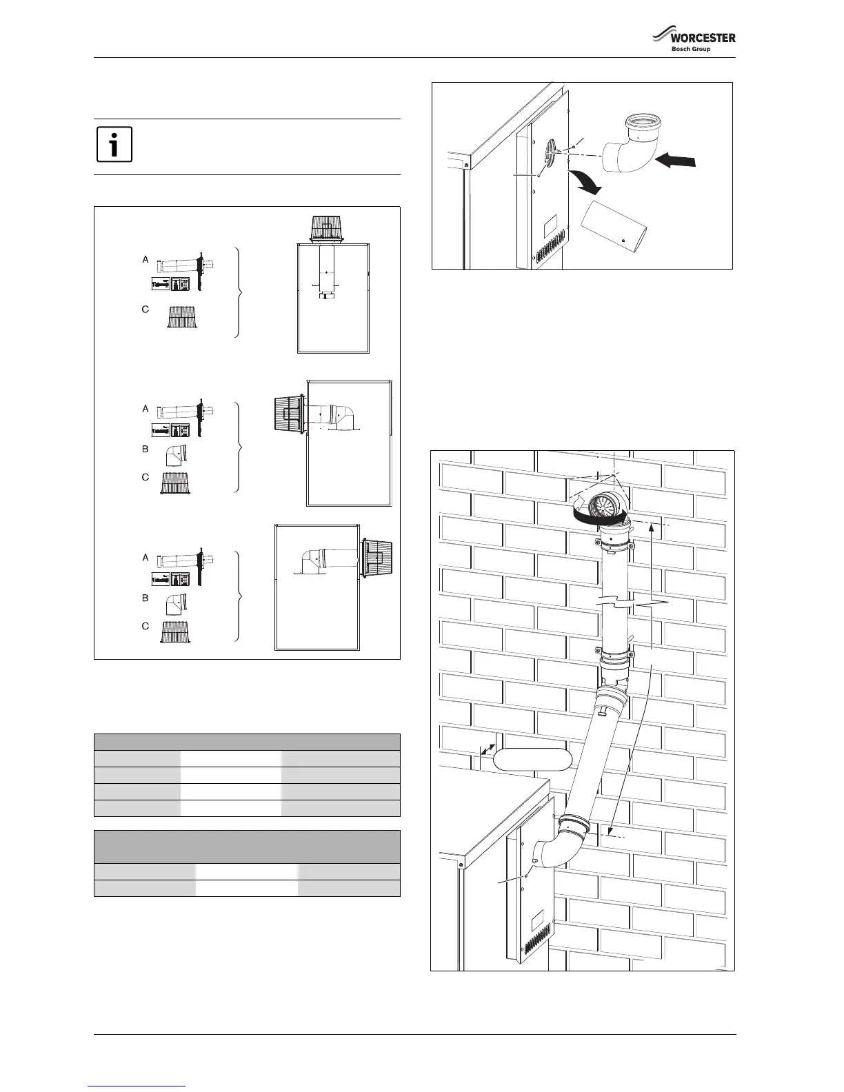
4.8.1 Cabinet mounted balanced horizontal flue options
• The horizontal flue is fitted to the rear or either side of the cabinet.
Fig. 21 Flue options
4.8.2 Plume management
1. Measure the plume management flue (M) from the centre of terminal,
along the required route to the centre of the plume outlet.
Fitting the terminal plume management kit
1. Remove and retain the screws that secure the terminal end into the
flue.
2. Discard the terminal end.
3. Fit the terminal elbow into the flue but do not secure with the screws
until the plume management system has been assembled.
Fig. 22 Fitting the terminal bend
1. Connect the sections of the plume management for desired length.
– Screw the clamp into the wall.
– Push the extension/s tube fully into the 90° bend, then withdraw
the tube by approximately 10mm to allow for expansion.
2. Once the plume management system is in place and secured to the
wall, secure the terminal bend with the screws remove earlier.
▶ The terminal end can be positioned up to 45° either side of the
central position, for plume re-direction.
▶ Adjust the plume management terminal end into the desired position
and secure with the screws provided.
Fig. 23 Plume management detail
It is strongly recommended that the flue terminal faces
away from walls to minimise the occurrence of wetting.
Heatslave II Flue length (L) Plume length (M)
12/18 & 18/25 160 - 2000mm 500 - 5000mm
Bends maximum of 2 maximum of 2
25/32 160 - 2000mm 500 - 4000mm
Bends maximum of 2 maximum of 2
Effective lengths of elbows
Bend Flue Plume
90° 1000mm 1000mm
45° 500mm 500mm
Table 5 Effective lengths of bends

 Loading...