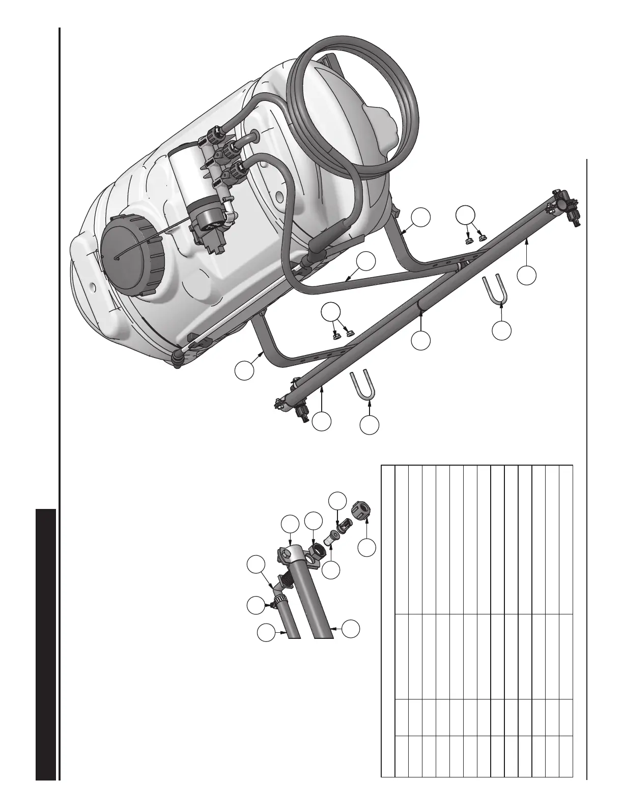
— SPRAY BOOM ASSEMBLY
PRECISION SPRAY EQUIPMENT
®
, a divison of Green Leaf, Inc. 9490 N BALDWIN ST FONTANET, IN 47851 www.workhorsesprayers.com 888-433-6631
a division of Green Leaf, Inc
®
PRECISION SPRAY EQUIPMENT
PSE
®
PARTS LIST
DESCRIPTIONPART NUMBERQTYITEM
Spray Boom Assembly63002221
Boom Insert
600256
1
2
ATV Angle Bracket60019123
φ1/4" U-Bolt w/ Nuts
60016924
B 11-34 R60011325
NTL38 P Fitting60011226
N1116 P Nut6001162
7
Check Valve / Strainer60011728
FT Spray Tip60011829
8027 P Nut600119210
Boom Hose Assembly
600115111
5/8" Hose Clamp
600120412
2.0--Insert ATV Angle Brackets into ATV Mounts as Ilustrated
2.1--Attach Spray Boom Assembly to ATV Angle Brackets using
U-Bolts with nuts at desired height.
2.2--Install Boom Clamps onto each end of the Spray Boom Assembly
and tighten screws. (screws should be on top of the Spray Boom)
2.3--Install Hose Clamps over each end of the Boom Hose assembly
as illustrated and press hose
ends onto NTL38P Fittings. Then
tighten down Hose Clamps to secure the fittings to the Hose
Assembly.
2.4--Insert the NTL38P Fittings through the the holes on the Boom
Clamps that were previously installed on the Spray Boom.
Secure in place with N1116 P Nuts.
2.5--Insert Check Valves/Strainers into the NTL38P Fittings.
2.6--Insert Spray Tips into 8027 P Nuts and then screw
nuts onto
fittings. (assure that tips are oriented downward to achieve the
correct spray pattern.
1
11
12
6
5
10
9
8
7
44
44
4
4
1
11
3
3
1
2
 Loading...