The Wormald FirePro Aerosol System, Model 08451, is a combined detection and extinguishant system designed for fire suppression in both marine (AMSA NSCV) and vehicle installations (AS5062). It features a Fire Control Panel (FCP) that integrates various functions for comprehensive fire protection.
Function Description:
The core of the system is the FP-08451 Fire Control Panel, which monitors two detection circuits, controls an extinguishing discharge circuit, and manages a siren/strobe circuit. It also includes an agent release notification circuit. The system supports programmable activation, allowing for either automatic or manual discharge. A built-in fault monitoring system continuously checks the system's integrity, and an isolation function allows for temporary disabling of automatic activation during maintenance or specific operational scenarios.
FirePro Aerosol Generators, which use the latest generation FPC solid compound, are the extinguishing agents. Upon activation, this compound transforms into a rapidly expanding, highly efficient gas based on Potassium salts. This gas does not deplete oxygen levels and is non-corrosive and non-toxic, with zero Ozone Depletion Potential (O.D.P.), Atmospheric Life Time (A.L.T.), and Global Warming Potential (G.W.P.). The system incorporates a fail-safe activation mechanism, ensuring generator operation even if other components fail. The FPC block changes to a potassium-based gas at 300°C to extinguish fires.
In the event of a fire, the system initiates an alarm condition, activates the siren/strobe, and can trigger equipment shutdown relays if installed. Personnel should evacuate, alert the Fire Brigade, and close all hatches, openings, engines, and extraction fans. Manual activation is achieved by pressing and holding both mode switches for 5 seconds. Automatic activation occurs when fire is detected on Circuit 1 Alarm. After discharge, the suppression gas should be contained within the risk area until the fire is extinguished and cannot reignite. Engine or fans should not be started until the fire is out. Cleanup after discharge is recommended with soapy water and a citric acid-based cleaning agent. All installed FirePro Generators and Thermal Fuse Couplings must be replaced after a discharge.
Important Technical Specifications:
- Dimensions: 148L x 84W x 35D mm
- Material: Diecast Aluminium, UV Tolerant
- Ingress Protection: IP65
- Operating Temperature: -40 to 85 degrees Celsius
- Power Supply Input: Compatible with 12-30VDC. Mains Operating Current is 20mA on 12V and 23mA on 24V. Backup power options are available via FP-08870/08871/08872 Power Control Modules.
- Detection Zones: 2 zones, operating at 12-30VDC.
- Detection End-of-line: 22kΩ Resistor.
- Maximum Detectors per Zone: Up to 30 conventional detectors, 100m linear heat detection cable, or 30 manual actuators.
- Alarm Threshold: 3.6V Fault sensing threshold (0.53V).
- Compatible Detectors: Hochiki SLV-AS Smoke Detector, Hochiki DCD-AE3M Thermal Detector, 14053 Manual Actuator, 09510 180°C Linear Heat Detection.
- Discharge Output Current: 2A at 12VDC, 4A at 24VDC.
- Discharge End-of-line: 3k3Ω Resistor.
- Maximum FirePro Generators: 2 in series at 12VDC, 4 in series at 24VDC.
- Standard Discharge Delay: 5 seconds from automatic/manual activation.
- Siren/Strobe Output Current: Max 0.5A, with 0.5A poly-switch resettable fuse.
- Siren/Strobe End-of-line: 1N4004 Diode.
- Maximum Siren/Strobes: 5.
- Compatible Siren/Strobes: Flashni Xenon Sounder Beacon.
- Agent Released Input: Thermal Switch, NC, Latching, Non-resettable. Thermal Event >80°C.
- Fault Monitoring: External faults include open/closed circuits for Circuit 1 Alarm, Circuit 2 Alarm, Siren/Strobe, and Discharge. Internal faults include poly-switch fuse operation, loss of internal 5V supply, and internal microprocessor malfunction.
Usage Features:
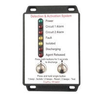
- LED Indicators: The control panel provides clear LED indicators for Power, Circuit 1 Alarm, Circuit 2 Alarm, Fault, Isolated, Discharging, and Agent Released states.
- Isolate Function: Pressing and holding Mode Switch 1 until one beep is heard isolates the control panel, illuminating the "Isolated" LED. This disables automatic activation but keeps manual activation operational. The panel continues to monitor for alarms and faults, sounding a 1-second beep for status changes while remaining isolated.
- Reset Function: Holding Mode Switch 1 until two beeps are heard resets the control panel, which then automatically isolates. The panel cannot be reset if the activation sequence has been initiated or while the "Discharging" LED is illuminated.
- Test Function: Holding Mode Switch 1 until three beeps are heard activates a test function, illuminating all LEDs, operating the internal sounder, and any external siren/strobes for 2 seconds, then returning to normal operation. This does not activate the suppression system.
- Manual Discharge: Pressing and holding both Mode Switches 1 and 2 continuously for 5 seconds manually discharges the fire system, activating sirens/strobes and shutdown relays. This should only be done during commissioning/servicing with the system isolated, or in a real fire event.
- Alarm Silence: Holding Mode Switch 1 until one beep is heard and the "Isolated" LED illuminates silences the internal sounder and any installed siren/strobes, and overrides shutdown relays. The panel remains in alarm/fault condition until serviced and reset.
- Programming: DIP switches inside the panel allow selection of four modes: Standard Discharge (power applied for 2 seconds, default), Extended Discharge (power applied for 240 seconds, for use with FP-08850 Discharge Delay Module), Manual Discharge (detectors operate siren/strobe only), and Automatic Discharge (detection on Circuit 1 Alarm discharges system, default).
- Connectivity: Deutsch Plugs are used for waterproof connections. Splitter Leads (FP-08919) enable connecting multiple FirePro generators to a single output.
- Mounting: The panel is mounted via four bolts/screws through flanges. No penetrations should be made through the casing. A Dash Mount Bracket (FP-08451B) is available.
Maintenance Features:
- Daily Service Schedule: Operators should perform a visual inspection of the control panel and installed components daily to ensure normal functioning (only "Power" LED green) and check anti-tamper seals/travel pins.
- Semi-annual / Annual Service Schedule: Servicing by accredited technicians every 6 months (AS1851 and AS5062) includes visual inspection of all components, verification of stream lengths and thermal clearances, and operational testing of the fire system.
- Logbook: A logbook must be maintained, recording general details, devices used, inspection dates and outcomes, risk assessments, schematic diagrams, installation photos, control panel programming, and inspection reports.
- Troubleshooting: The fault monitoring system detects open circuits in detection, siren/strobe, discharge, and agent released circuits, as well as internal malfunctions. Faults are indicated by the "Fault" LED and an internal sounder with coded beeps (1 beep for Circuit 1 Alarm, 2 beeps for Circuit 2 Alarm, 3 beeps for Discharge Circuit or Siren/Strobe Circuit). Internal faults (continuous steady or pulsing beep) cannot be isolated and may require powering down/up or supplier contact. External faults can be isolated and require inspection and testing of connections and components, using end-of-line plugs for systematic checking.
- Discharge Testing: Commissioning and test procedures include isolating the panel, disconnecting generators, connecting an FP-08800 Test Module, cleaning components, inspecting generators and mounting brackets, checking manual actuators and detection systems, verifying labels, testing fault monitoring by disconnecting circuits, and performing manual discharge tests. External device discharge tests involve activating detectors or manual actuators.
- Battery Replacement: Backup batteries should be replaced every 2 years.
- Design Survey & Risk Assessment: Annual design surveys and risk assessments (every 5 years or after incidents) are required to ensure system compliance with baseline data and operating conditions.