Page | 12
6. Discharge Circuit: This circuit should remain disconnected until all other circuits are
connected. The control panel must not be in an alarm/fault condition when the FirePro
generators are connected, as this may cause an accidental discharge. A Test Module (P/N
FP-08800) should be connected to take the control panel out of fault condition and for any
commissioning.
- Mounting FirePro Generators: FirePro Generators must be installed using only
approved brackets with observation of the relevant stream lengths and thermal
clearances noted in the design calculation and risk assessment. Generators should be
mounted near the top of the risk area, with care taken to aim generators away from
openings or obstacles that may impede dispersion of the suppression agent. Egress
routes for personnel must be kept clear, and not be obstructed by any installed
components or by agent dispersion.
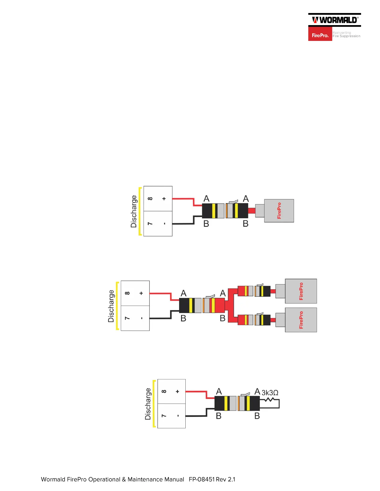
- Connecting FirePro Generators: If a single FirePro Generator is being installed, it
can be connected directly to the Discharge output on the control panel.
If multiple FirePro Generators are being installed on a single output, they must be
connected using the FP-08919 Splitter Lead. See 3.4 Discharge Output, for design
considerations when connecting multiple FirePro generators. The maximum number of
FirePro Generators that can be connected will depend on the main power supply.
- Discharge Not Used: If the discharge circuit is not used, the supplied end-of-line
resistor (3k3Ω) must be connected to the Discharge output using the supplied deutsch
plugs.
 Loading...