Page | 9
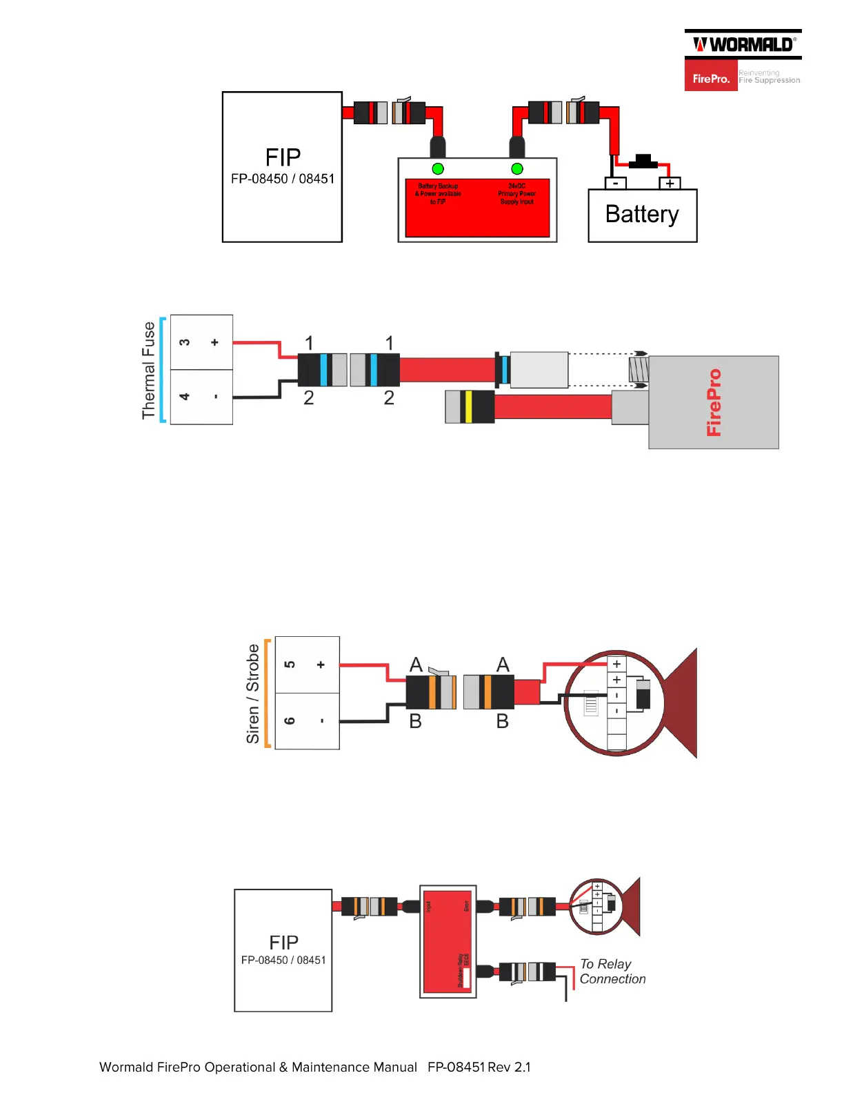
2. Agent Released Circuit: The Thermal Fuse Coupling (P/N FP-08825) should be screwed
into the thermal port on one of the installed FirePro generators and connected to the control
panel.
3. Siren/Strobe Circuit: Mount the siren/strobe (P/N FP-08940) in a location where it is
visible and audible in all points with the risk area and connect to the “Siren” output on the
module (marked orange). If more than one siren/strobe is being installed, they are to be
connected using the secondary positive/negative terminals in the sounder.
The supplied end-of-line diode should be installed in the secondary positive/negative
terminals of the last siren/strobe in the circuit. The diode is polarised, so the positive lead
of the diode (marked with a grey band) should be terminated in the positive terminal of
the siren/strobe, otherwise a fault will occur on the fire control panel.
Where a Siren & Shutdown Module (FP-08860) is used, the module should be connected
to the “Siren/Strobe” output on the control panel. The siren/strobe should be connected
to the “Siren” output on the module (marked orange) and the relay connected using the
“Shutdown Relay” output (marked white). See FP-08860 product manual for
further details.
 Loading...