BASE UNIT
150 - 300 Pull Out
Assembly Guide
For Internal Use: FI.WR.INS.029_WKIN00101_BASE_PullOut_150-300_1Dr_Rev4.indd
Page 3
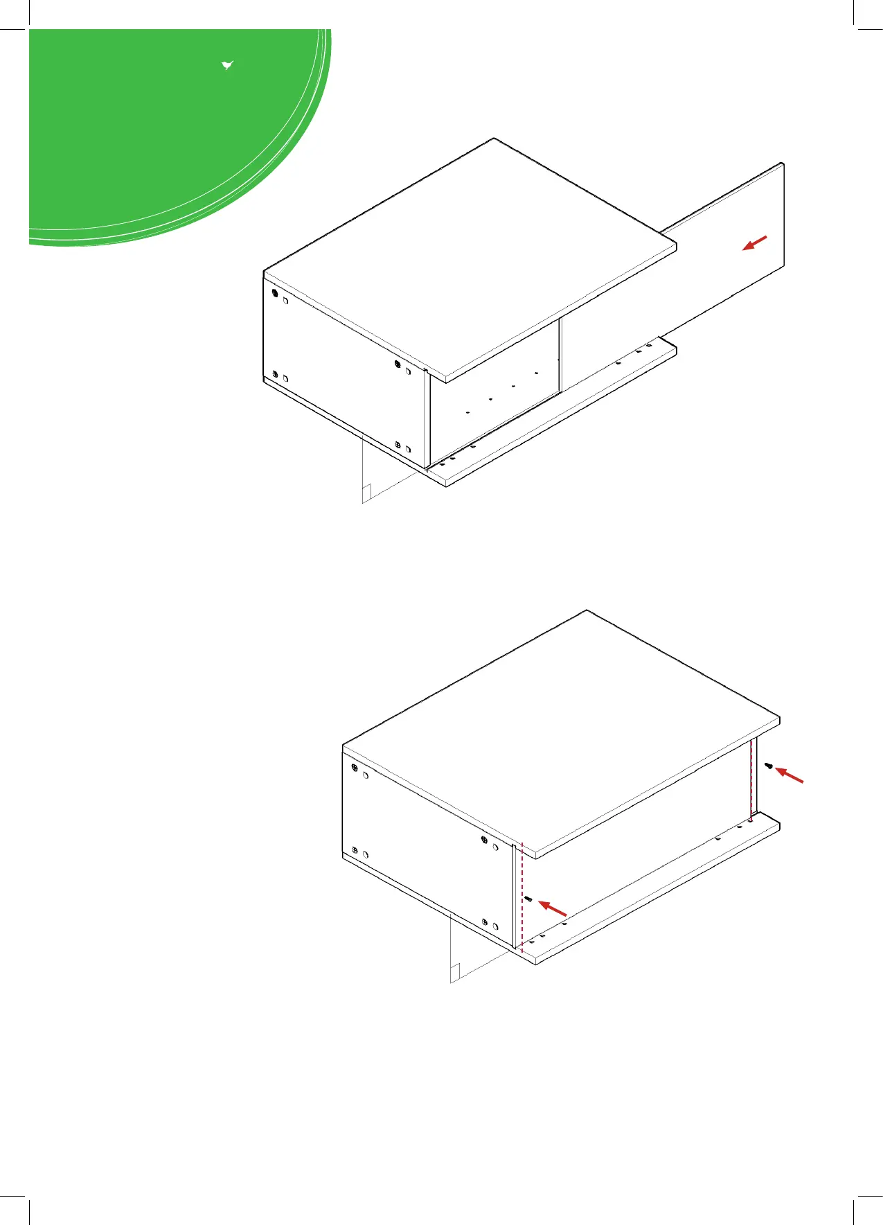
Step 5.
Slide back panel (A) into
groove of end panels (B).
Once back panel (A) is in position, ensure
the panel is ush & square with bottom
of end panels (B).
Step 6.
Ensure carcass is square.
Hand tighten all cam locks (H), this will
expand cam dowels (G) and tighten the
unit together.
Step 7.
Secure back panel (A) with 2 x 30mm
screws (K) equally spaced at the top &
bottom of back panel (A) into both xed
panels (C), as shown.
Ensure you screw into the centres of the
base panels (C) (9mm from the edge).
B
C
A
B
A
C
K
K
B
9mm
9mm
 Loading...