Home
wsm
Tractor
M6060
wsm M6060 User Manual
4
of 1
of 1 rating
639 pages
Give review
Manual
Specs
To Next Page
To Next Page
To Previous Page
To Previous Page
Loading...
TRANSMISSION
M6060, M7060, WSM
2-S13
(2)
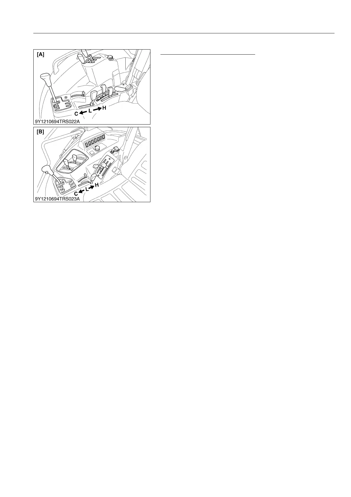
Range/Creep Gear Shift
Checking Function of Rang
e Shift
1.
Check the function of the range gear shift.
•
H
,
L
and
C
position.
2.
If feeling abnormal shifting, adjust the range sh
ift following
pages.
9Y1210828TRS0008US0
H :
Hi Speed Range Position
L :
Lo Speed Range Positio
n
C :
Creep Speed Range Position
[A]
ROPS Model
[B]
CABIN Model
KiSC issued 08, 2013 A
275
277
Table of Contents
Information
4
Table of Contents
4
Safety First
5
Safety Decals
5
Safety Decals
8
Specifications
14
Traveling Speeds
18
Dimensions
19
General
22
1 Tractor Identification
24
Model Name and Serial Numbers
24
ROPS Model
24
CABIN Model
25
Engine Serial Number
26
DPF Muffler Number
27
E4B Engine
29
Cylinder Number
29
2 General Precautions
30
3 Handling Precautions for Electrical Parts and Wiring
31
Wiring
31
Battery
33
Fuse
33
Connector
33
Handling of Circuit Tester
34
Color of Wiring
35
4 Lubricants, Fuel and Coolant
36
5 Tightening Torques
38
General Use Screws, Bolts and Nuts
38
Stud Bolts
38
Hydraulic Fittings
39
Hydraulic Hose Fittings
39
Hydraulic Pipe Cap Nuts
39
Adaptors, Elbows and Others
39
Metric Screws, Bolts and Nuts
40
American Standard Screws, Bolts and Nuts with Unc or Unf Threads
40
Plugs
40
6 Maintenance
41
7 Check and Maintenance
44
Daily Check
44
Check Points of Initial 50 Hours
45
Check Points of Every 50 Hours
46
Check Points of Every 100 Hours
48
Check Points of Every 200 Hours
54
Check Point of Every 400 Hours
57
Check Points of Every 500 Hours
57
Check Point of Every 600 Hours
58
Check Points of Every 1000 Hours
59
Check Points of Every 1500 Hours
60
Check Points of Every 3000 Hours
61
Check Points of Every 1 Year
61
Check Points of Every 2 Years
63
Others
67
8 Special Tools
74
Special Tools for Engine
74
Special Tools for Tractor
94
Special Tools for Air Conditioner Unit
111
9 Tires
114
Tire Size and Inflation Pressure
114
Tread Adjustment
116
Front Wheels
116
Adjusting Front Wheel Turning Stopper Bolt (for SPAIN Model
118
Rear Wheels
119
Wheel Hub
121
Tire Liquid Injection
121
10 Implement Limitations
125
Trailer Load Capacity
128
Front Loader
131
Mechanism
133
1 Feature
134
2 Engine Body
135
Cylinder Block
135
Cooling Jacket
135
Half-Floating Head Cover
136
Cylinder Head
136
Screws Per each Cylinder Assembling Structure
137
Center Direct Injection System (E-Cdis)
138
Gear Train Configuration
138
Piston
139
Built-In Dynamic Balancer
139
3 Lubricating System
140
Oil Cooler
140
4 Cooling System
141
Thermostat
141
Bottom Bypass System
142
5 Fuel System
143
Overview
143
Supply Pump
144
Rail
147
Injector
148
Engine Control System
151
Engine ECU
152
Sensor
152
6 Egr System
154
Egr Valve
154
Reed Valve
154
Egr Cooler
155
7 After Treatment System
156
After Treatment Devices
156
Servicing
161
Troubleshooting
162
Servicing Specifications
165
Tightening Torques
170
Checking, Disassembling and Servicing
172
Checking and Adjusting
172
Engine Body
172
Lubricating System
174
Cooling System
175
Turbocharger
177
EGR Cooler
178
Preparation
179
Bonnet and Cover
179
DPF Muffler
180
Lubricant and Coolant
183
Propeller Shaft and Power Steering Hose
184
Separating Engine from Clutch Housing (ROPS Model)
185
Separating Engine from Clutch Housing (CABIN Model)
187
Separating Engine from Front Axle Frame
190
Disassembling and Assembling
191
External Components
191
Turbocharger and EGR
191
Common Rail
193
Cylinder Head and Valves
195
Thermostat
201
Supply Pump
202
Water Pump and Oil Cooler
205
Front Cover
206
Flywheel and Timing Gears
207
Piston and Connecting Rod
212
Crankshaft and Crankcase
215
Servicing
217
Cylinder Head and Valves
217
Timing Gears
223
Piston and Connecting Rod
229
Crankshaft
231
Connecting Rod
233
Cylinder
237
Oil Pump
237
Relief Valve
238
Mechanism
240
1 Structure
241
F18/R18 Speed Transmission Model
241
Live Pto-Ground Pto Model (Ita Model)
242
2 Power Train for Traveling Gear
243
Shuttle Shift Section
243
Structure
243
Oil Flow
244
Hydraulic Clutch Pack
245
Hydraulic Shuttle Valve
246
Structure
246
Operation
247
Main Gear Shift Section
252
Hi-Lo-Creep Shift Section
253
Shift Fork Rod and Fork
254
3 Lubrication for Transmission
255
Hydraulic Shuttle Model
255
4 Power Train for Pto System
256
Pto Gear Section
256
Ground Pto and Live Pto Section (Ita Model)
257
Pto Hydraulic Clutch Section
258
PTO Hydraulic Clutch
258
PTO Solenoid Valve, Relief Valve and Oil Flow
259
5 Power Train for 4Wd
260
4Wd Hydraulic Clutch Section
260
4Wd Oil Flow
261
Servicing
262
1 Troubleshooting
264
2 Servicing Specifications
266
3 Tightening Torques
269
4 Checking and Adjusting
270
Shuttle Lever
270
Shuttle Lever Neutral Position
270
Engine Start Condition
272
Clutch Pedal Free Travel
273
Gear Shifting Linkage
274
Main Gear Shift
274
Range/Creep Gear Shift
276
Shuttle Valve
278
2Wd-4Wd Clutch
279
Pto Clutch
280
Accelerator Section
281
Checking Accelerator Lever
281
Adjusting Accelerator Lever and Wire
283
5 Disassembling and Assembling
285
Hydraulic Shuttle Valve and Solenoid Valve Assembly
285
Removing Fuel Tank (ROPS Model)
285
Removing Fuel Tank (CABIN Model)
285
Hydraulic Shuttle Valve
287
Solenoid Valve Assembly
287
Preparation for Separating each Block
288
Lubricant and Coolant
288
4WD Propeller Shaft and Power Steering Hose
288
Front Axle Rocking Restrictor
289
Bonnet (ROPS Model)
289
Bonnet (CABIN Model)
289
Separating Engine and Clutch Housing Case
289
ROPS Model
289
CABIN Model
289
Separating Clutch Housing Case from Transmission Case
290
Preparation for ROPS Model
290
Preparation for CABIN Model
294
Separating Transmission Case
295
Damper Disc
296
Hydraulic Shuttle Clutch
296
Shift Cover
298
Clutch Housing
301
Creep Gear Assembly
301
1St Shaft, 2Nd Shaft and 3Rd Shaft
301
1St Shaft
304
2Nd Shaft
305
3Rd Shaft
305
Removing DT Propeller Shaft
306
Transmission Case
306
Removing Solenoid Valve Assembly
306
PTO Clutch Pack
307
Disassembling PTO Clutch Pack
308
Removing 4WD Clutch
309
Disassembling 4WD Clutch Pack
311
Removing Differential Gear and Bevel Pinion Shaft
312
Differential Gear
315
Pto Gear Case
317
Ground Pto and Live Pto
318
6 Servicing
320
Bearing, Shift Fork and Synchronizer
320
Traveling Clutch
321
Shuttle Clutch Pack
322
Shaft and Gear
322
4Wd Clutch Pack
323
Pto Clutch Pack
324
Differential Gear
325
Spiral Bevel Pinion Shaft
325
Backlash and Tooth Contact (Except ITA Model)
326
Backlash and Tooth Contact (ITA Model)
328
Differential Case Differential Pinion Gear and Differential Side Gear
330
Differntial Lock Shifter
331
Rear Axle
332
Servicing
335
1 Troubleshooting
336
2 Servicing Specifications
337
3 Tightening Torques
338
4 Disassembling and Assembling
339
Preparation for Disassembling and Assembling Valve
339
Separating Rear Axle (Rops Model)
340
Separating Rear Axle (Cabin Model)
342
Disassembling Rear Axle
345
Brake Section
345
Rear Axle Case
345
5 Servicing
348
Bearing
348
Planetary Gear
348
Mechanism
351
1 Travelling Brake
352
Structure (Hydraulic Brake Model)
352
Master Cylinder Assembly
354
Hydraulic Trailer Brake Valve
355
Structure
355
Operation
356
2 Parking Brake
360
Inner Structure
360
Fixing Flow
361
Servicing
363
Troubleshooting
364
Servicing Specifications
365
Tightening Torques
366
Checking, Disassembling and Servicing
367
Checking and Adjusting
367
Traveling Brake
367
Parking Brake Gear
369
Parking Brake
371
Disassembling and Assembling
372
Preparation for Disassembling Master Cylinder and Brake Pedal (ROPS Model)
372
Preparation for Disassembling Master Cylinder and Brake Pedal (CABIN Model)
373
Removing Master Cylinder (ROPS Model)
375
Removing Master Cylinder (CABIN Model)
375
Master Cylinder
376
Brake Pedal
377
Brake Piston
378
Brake Disk and Plate
379
Parking Brake Gear
380
Servicing
381
Brake Pedal
381
Traveling Brake
382
Front Axle
383
Servicing
387
Troubleshooting
388
Servicing Specifications
389
Tightening Torques
391
Checking, Disassembling and Servicing
392
Checking and Adjusting
392
Disassembling and Assembling
393
Separating Front Axle [4WD Model]
393
Disassembling Front Axle [4WD Model]
395
Removing Differential Gear and Bevel Pinion Shaft
398
Disassembling Differential Gear (LSD)
399
Servicing
401
Steering Cylinder
413
Servicing
414
Troubleshooting
415
Servicing Specifications
416
Tightening Torques
417
Checking, Disassembling and Servicing
418
Checking and Adjusting
418
Steering Controller
418
Hydraulic Pump
418
Preparation
419
Removing Power Steering Hydraulic Pump
419
Removing Steering Wheel
419
Removing Power Steering Controller (ROPS Model)
419
Removing Steering Controller (CABIN Model)
420
Removing Steering Cylinder
422
Disassembling and Assembling
424
Hydraulic Pump
424
Steering Controller
424
Disassembling Steering Cylinder
427
Servicing
427
Hydraulic System
428
Mechanism
429
1 Structure
430
F18/R18 Speed Transmission Model (Rops Model)
433
2 Hydraulic Circuit
433
Total Hydraulic Circuit
433
3 Three Point Hitch Hydraulic System
434
Three Point Hitch Hydraulic Circuit
434
Hydraulic Block
435
Linkage Mechanism
436
Position Control
437
Draft Control
438
Mixed Control
440
Hydraulic Cylinder
440
Servicing
441
2 Servicing Specifications
443
3 Tightening Torques
445
4 Checking and Adjusting
446
Hydraulic Pump
446
Relief and Safety Valve
448
Position and Draft Control Linkage
450
Auxiliary Control Valve Linkage
457
Oil Cooler Check Valve (for F18/R18 Speed Transmission Model)
458
5 Disassembling and Assembling
459
Hydraulic Pump
459
Three Point Hitch Hydraulic Block Assembly
460
Removing 3-Point Hitch Hydraulic Block (ROPS Model)
460
Removing 3-Point Hitch Hydraulic Block (CABIN Model)
461
Hydraulic Linkage
462
Control Valve
466
Hydraulic Cylinder
467
Relief Valve
469
Safety Valve
469
Top Link Bracket
470
Lift Arm and Lift Arm Shaft
470
Lowering Speed Adjusting Valve and Check Valve
471
6 Servicing
472
Lift Arm and Top Link Bracket
472
Mechanism
475
1 Electrical Circuit Diagram
476
Rops Model
476
Starting System and Charging System
476
Lighting System
477
Instrument Panel Board (Meter Panel)
478
Main Control System (Tractor ECU)
479
Engine Control System 1 (Engine ECU)
480
Engine Control System 2 (Engine ECU)
481
Cabin Model
482
Starting System and Charging System
482
Lighting System
483
4WD (Transmission Control) System
484
Instrument Panel Board (Meter Panel)
485
Working Light and Radio
486
Air Conditioner
487
Wiper System
488
Main Control System (Tractor ECU)
489
Engine Control System 1 (Engine ECU)
490
Engine Control System 2 (Engine ECU)
491
2 Starting System
492
System Outline and Electrical Circuit
492
ROPS Model
492
CABIN Model
493
3 Instrument Panel
494
Indication Items of Meter Panel
494
ROPS Model
494
CABIN Model
495
Easy Checker
496
Lcd Monitor Indication
497
ERROR Mode
498
Setting Mode
499
Testing Mode
499
ECO 40 Km/H FUNCTION
500
Structure
500
Components
501
Pto Speed Limiter (if Equipped 540Economy)
502
Structure
502
Components
503
Constant Rpm Management Switch with Indicator (Work Cruise)
505
Structure
505
Servicing
508
4 Lighting System
511
Flasher Unit
515
2 Servicing Specifications
515
3 Tightening Torques
516
4 Checking and Adjusting
517
Battery, Fuses, Grounding and Connector
517
Battery
517
Fuse
519
Checking Grounding Wires
522
Connector
523
Main Switch
523
ROPS Model
523
CABIN Model
524
Glow Plug
526
Starter Motor
526
Alternator
527
Throttle Sensor
529
Meter Panel
531
Setting Mode
531
Adjusting Meter Panel
532
Adjusting Throttle Sensor
533
Testing Mode
535
Checking Error Code
536
Selecting Tractor Specification
537
Tractor Ecu
540
Connector Pin (44 Pin)
542
Traveling Switch and Sensor
543
Engine Switch and Sensor
548
Relays
552
Starter Relay and Glow Relay
552
Relays
553
Lighting Switches and Flasher Unit
555
Combination Switch (ROPS Model)
555
Lever Combination Switch and Horn Switch (CABIN Model)
556
Hazard Switch
557
Flasher Unit
558
Front Work Light Switch (ROPS Model)
559
Front/Rear Work Light (CABIN Model)
560
Solenoid Valve
561
Pto
561
Trailer Brake (ITA Model)
562
Opc (Operator Presence Control) System
562
Pto Switch
564
5 Disassembling and Assembling
565
Starter Motor
565
Alternator
565
Fuse (Slow Blow 100 A) for Cabin Model
567
6 Servicing
568
Starter
568
Mechanism
573
Air Condiitioning System
574
Structure
574
Compressor
575
Air Conditioner Unit
576
System Control
577
Air Control Vent
578
Air Flow
578
Electrical System
579
Electrical Circuit
579
Blower Relay and Compressor Relay
580
Blower Relay
581
Servicing
582
2 Servicing Specifications
587
4 Precautions at Repairing Refrigerant Cycle
589
Handling of Service Tools
590
Manifold Gauge Set
590
Refrigerant Charging Hose
592
Vacuum Pump Adaptor
593
Electric Gas Leak Tester
593
Can Tap Valve
593
T-Joint
594
R134A Refrigerant Recover and Recycling Machine
594
5 Checking and Charging Refrigerant Cycle
595
Checking with Manifold Gauge
595
Discharging, Evacuating and Charging
600
Discharging the Refrigerant
600
Evacuating the System
601
Charging the Refrigerant
602
Checking Charge Refrigerant Amount
604
6 Checking, Disassembling and Servicing
605
Checking and Adjusting
605
Compressor
605
Relay (A/C Compressor, Front Working Light, Front Wiper, Blower, Blower Hi, ACC, Auxiliary Power)
605
Wiper Relay
606
Control Panel (Blower Switch, A/C Switch, Mode Control Dial, Temperature Control Dial and Recirculation/Fresh Air Selection Switch)
607
Blower Resistor
610
Blower Motor
610
Temperature Motor
611
Mode Motor
611
Recirculation/Fresh Air Motor
612
Pressure Switch
613
Front Wiper Switch
614
Front Wiper Motor
614
Rear Wiper Switch (if Equipped)
615
Rear Wiper Motor (if Equipped)
615
Disassembling and Assembling
616
Separating Cabin from Tractor
616
Removing Compressor Assembly
624
Removing Air Conditioner Unit
627
Removing Air Conditioner Hose
630
Removing Heater Hoses
633
Cab Windshield
634
Wiper Motor
637
Servicing
638
4
Based on 1 rating
Ask a question
Give review
Questions and Answers:
Need help?
Do you have a question about the wsm M6060 and is the answer not in the manual?
Ask a question
wsm M6060 Specifications
General
Engine Power
60 hp
Drive
4WD
Engine Type
Diesel
PTO Power
50 hp
Hydraulic System
Open center
Type
Compact Utility Tractor
Related product manuals
wsm M108S
525 pages
wsm M7060
639 pages
wsm m9540
73 pages
wsm ME8200
543 pages
wsm L503
619 pages
wsm L3301
662 pages
wsm L3400
93 pages
wsm L2800
93 pages
wsm B2420
333 pages
wsm L3901
662 pages
wsm L3830
619 pages
wsm Kubota L4100
346 pages
 Loading...