3-1
3. Quick Start
This Quick Start Guide describes a simplified installation procedure for the
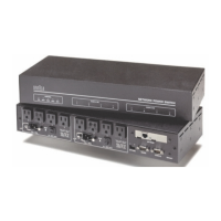
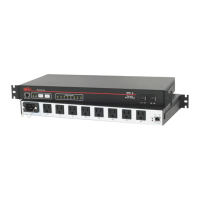
IPS-800, IPS-1600, IPS-800-CE and IPS-1600-CE hardware, which will allow
you to communicate with the unit in order to demonstrate basic features and
check for proper operation.
Note that this Quick Start Guide does not provide a detailed description of unit
configuration or discuss advanced operating features. For more information,
please refer to the Installation, Configuration and Operation sections in this
User's Guide.
3.1. Hardware Installation
3.1.1. Apply Power to the IPS
Refer to power rating nameplate on the IPS back panel, and then connect the
IPS unit to an appropriate power source. The IPS-800 and IPS-1600 should be
connected to a 100 to 115 VAC power supply, and the IPS-800-CE and
IPS-1600-CE should be connected to a 208 to 240 VAC power supply.
CAUTION: Prior to connecting power to the unit, make certain to
review the Safety Precautions listed in the beginning of this User's
Guide.
1. Note that the IPS features two separate AC inputs; connect the power
cables (supplied with the unit) to the unit's "Bus A" and "Bus B" Power
Inlets, then connect the cables to an appropriate power supply.
• Models IPS-800 and IPS-1600 will support up to 15 Amps maximum
per power circuit, for a total of 30 Amps. Models IPS-800-CE and
IPS-1600-CE will support up to 10 Amps maximum per power circuit,
for a total of 20 Amps.
2. Set the Main Power switch in the ON position; the ON LED should light,
and the RDY LED should begin to flash. This indicates that the IPS is
ready to receive commands.


 To Next Page