CRD-XP
CRD-XP_2006-04_EN Subject to technical changes Page 13 of 16
7 Error messages
In the event of malfunction, the display flashes with the error code. Depiction of the error code is
suppressed in the advanced level (point in lower right flashes).
Display Cause of malfunction Monitoring function and emergency program
F1
Short-circuit or incoming air
probe interrupted
Cooling command with defined operating time
(Parameters P42, P43)
F2
Short-circuit or limit probe
interrupted
With electric, hot gas or cold gas defrosting and a
defect in the limit probe, defrosting does not take place.
EE
Data error in non-volatile
memory
A power surge may destroy the set values. Operation
takes place with default settings.
Re-enter all memory locations!
Isolate thermostat!
COLL
Address collision on the bus The set address is already assigned.
Set a different address for the device !
buS
Bus error
No bus
Check bus connection or set address to 0 (P64)
door
Cold room door open too long Close cold room door!
AL
Alarm digital Input 1
Zero current principle,
alarm on loss of current at the input 1
dAL
Delayed alarm via input 1 Apply voltage to input 1,
rectify external fault
Uhr
Timer has invalid time on
address > 0
Restore bus connection to the gateway or enter time
(P16) and set address to 0 (P64)
-6
T flashing
Over or under-temperature
alarm of regulator actual value
Thermostat is too warm or too cold.
Check setting of over-temperature threshold P47 or
under-temperature threshold P48.
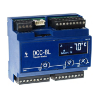
8 Service connection
For service and commissioning purposes, a laptop can be connected
directly to the cold location controller. The required connection
sockets for the communication bus are located to the left behind the
front plate. The CAN-PC901 – converter must be used for
communication with the computer.
A “service button” is located above the connection socket.
(Æ chapter 2)