CRD-XP
Page 2 of 16 Subject to technical changes CRD-XP_2005-12_EN
Table of Contents
Page
1 Connection diagrams 2
2 Operation 3
3 Description of parameters 4
4 Control 8
5 Fan control 10
6 Defrosting 11
7 Error messages 13
8 Service connection 13
9 Installation 14
10 Accessories 15
11 Technical data 15
12 Software revisions and validity of documentation 16
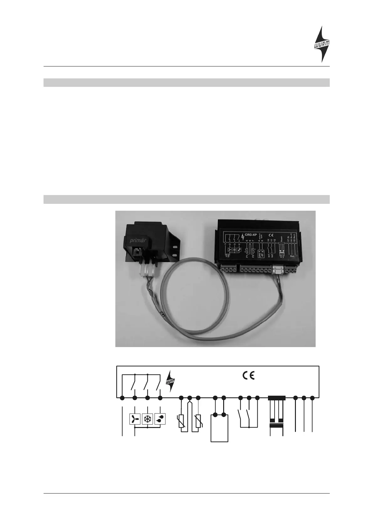
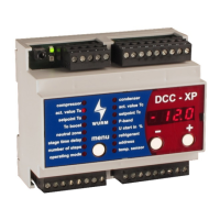
1 Connection diagrams
Photo showing cables connecting CRD-XP to transformer
1
2
3
4
5
10
17
88
6
11
18
99
7
12
19
CRD
-XP
CRD-XP
230
VAC
230
VAC
F1
F2
defrost
sync.
Bus L
Bus H
0V
Power
In1
In2
Bus
Connection terminals on CRD-XP
The wiring diagram applies to devices of Version 2.0 and higher.
Caution: On Version 1.0 and 1.1 devices, the cooling and fan output relays
have been designed to act as openers.