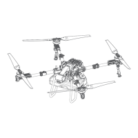
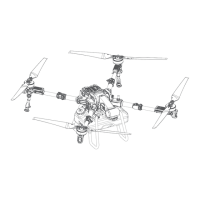
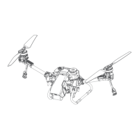
5
18
19
26
22
28
31
27
23
29
30
25 24
21
20
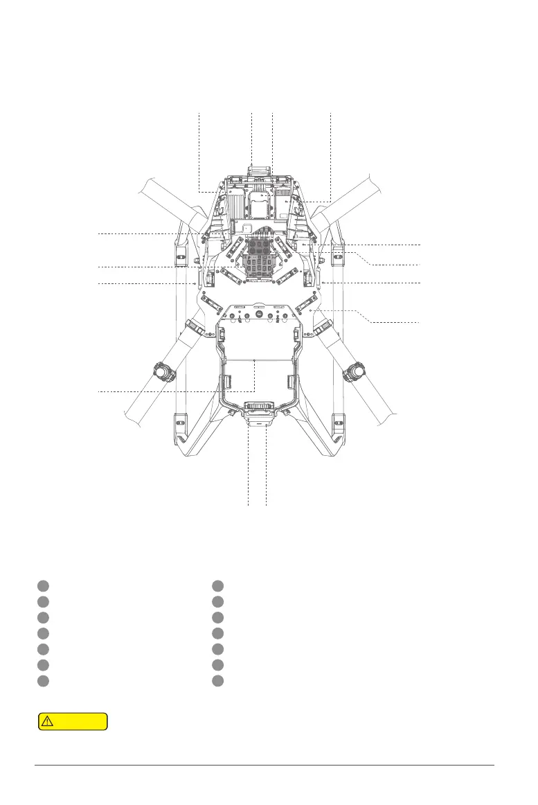
*The number of radar and XCope modules may vary depending on the UAV Version
There are corresponding labels on the upper plate of the fuselage and the aluminum sleeve
of the arm, and the numbers represent the orientation of the corresponding arm.
No.2 Arm
No.1 Arm
No.3 Arm No.4 Arm
23
20
18
24
21
19
22
Airframe orientation number
FC
RTK UAV module
Radar (Front)
Radar (Right)*
Antenna frame
Power grid Hub
25
26
27
28
29
30
31
HDLS module
Antenna Hub
Central Hub
Radar (Left)*
Airframe nameplate (serial number/QR code)
Flight status indicator (tail light) Radar (Rear)
Attention
Radar (Rear)
Figure 3.
Airframe module & Arm orientation