TABLE OF CONTENTS
2001 Xantrex Technology, Inc.
5916 - 195th Street N. E.
Arlington, WA 98223
Telephone: 360/435-8826
Fax: 360/435-2229
www.traceengineering.com
SW Series Inverter/Charger
Part No. 2031-5
Rev. C: February 2001
INDEX OF FIGURES
Figure 1, Identification Label .................................................................................................................. 7
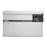
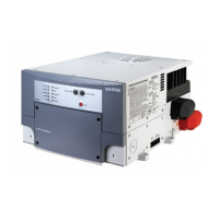
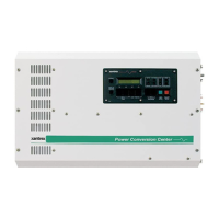
Figure 2, SW Series Inverter/Charger.................................................................................................... 9
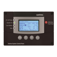
Figure 3, Control Panel........................................................................................................................... 9
Figure 4, AC Side ................................................................................................................................. 12
Figure 5, Internal Components and Indicators ..................................................................................... 13
Figure 6, Aux and Gen Control Relays................................................................................................. 14
Figure 7, DC Side................................................................................................................................. 14
Figure 8, Air Flow Intake Location........................................................................................................ 18
Figure 9, AC Input/Output Power Connection ......................................................................................19
Figure 10, Warning Label..................................................................................................................... 21
Figure 11, Battery to Inverter Cable Connection .................................................................................. 24
Figure 12, Neutral-To-Ground Bond Switching: No External AC Source Connected........................... 27
Figure 13, Neutral-To-Ground Bond Switching: External AC Source Connected ................................ 28
Figure 14, Neutral-To-Ground Bond Switching: Neutral Bonded To Ground....................................... 28
Figure 15, Multiple Point Ground System............................................................................................. 29
Figure 16, Single Point Ground System ............................................................................................... 29
Figure 17, Trace™ SW Series Inverter Simple Block Diagram ........................................................... 57
Figure 18, Trace™ SW Series Inverter Output Waveform................................................................... 58
Figure 19, Trace™ SW Series Efficiency Curves.................................................................................. 59
Figure 20, Inverter Capacity vs. Temperature...................................................................................... 60
Figure 21, Three-Stage Battery Charging ............................................................................................ 64
Figure 22, BTS (Battery Temperature Sensor) .................................................................................... 65
Figure 23, Two Wire Start Wiring Diagram .......................................................................................... 76
Figure 24, Three Wire Start Wiring Diagram (HONDA Type) .............................................................. 77
Figure 25, Three Wire Start Wiring Diagram (ONAN Type)................................................................. 77
Figure 26, Relay RY7 and RY8 Sequence ...........................................................................................78
Figure 27, Selling Power From A DC Charging Source; Hypothetical Time Of Day Oper. History...... 85
Figure 28, Selling Power Stored In The Batteries; Hypothetical Time Of Day Operational History...... 86
Figure 29, Utility Interactive Line-Tie System With Battery Backup Flow Diagram .............................. 88
Figure 30, Overvoltage Protection for Battery ...................................................................................... 89
Figure 31, Series Configuration: 6-Volt Battery Wiring....................................................................... 107
Figure 32, Series Configuration: 12-Volt Battery Wiring..................................................................... 107
Figure 33, Parallel Configuration: 12-Volt Battery Wiring................................................................... 108
Figure 34, Series-Parallel Configuration: 6-Volt Battery Wiring.......................................................... 109
Figure 35, Series-Parallel Configuration: 12-Volt Battery Wiring........................................................ 109
Figure 36, AC Waveforms.................................................................................................................. 116
Figure 37, SW Series Dimensions: With AC Access Covers – Showing Knockout Sizes ................. 120
Figure 38, Installation Diagram, 120 VAC, 1 Phase, Grid Connected, Generator Backup ................ 121
Figure 39, Installation Diagram, 240 VAC, 3 Wire, Grid Connected, Generator Backup................... 122
Figure 40, AWG Wire Size................................................................................................................. 131
 Loading...