©2000 Xantrex Technology Inc.
PV Charge Control Mode Cabling
Photovoltaic arrays generate current whenever light strikes the surface of
the array. Before connecting the C-Series controller, cover or disconnect the
array to prevent any current from being generated.
· Remove one or more of the knockout plugs on the controllers case and
feed the connecting wires through it.
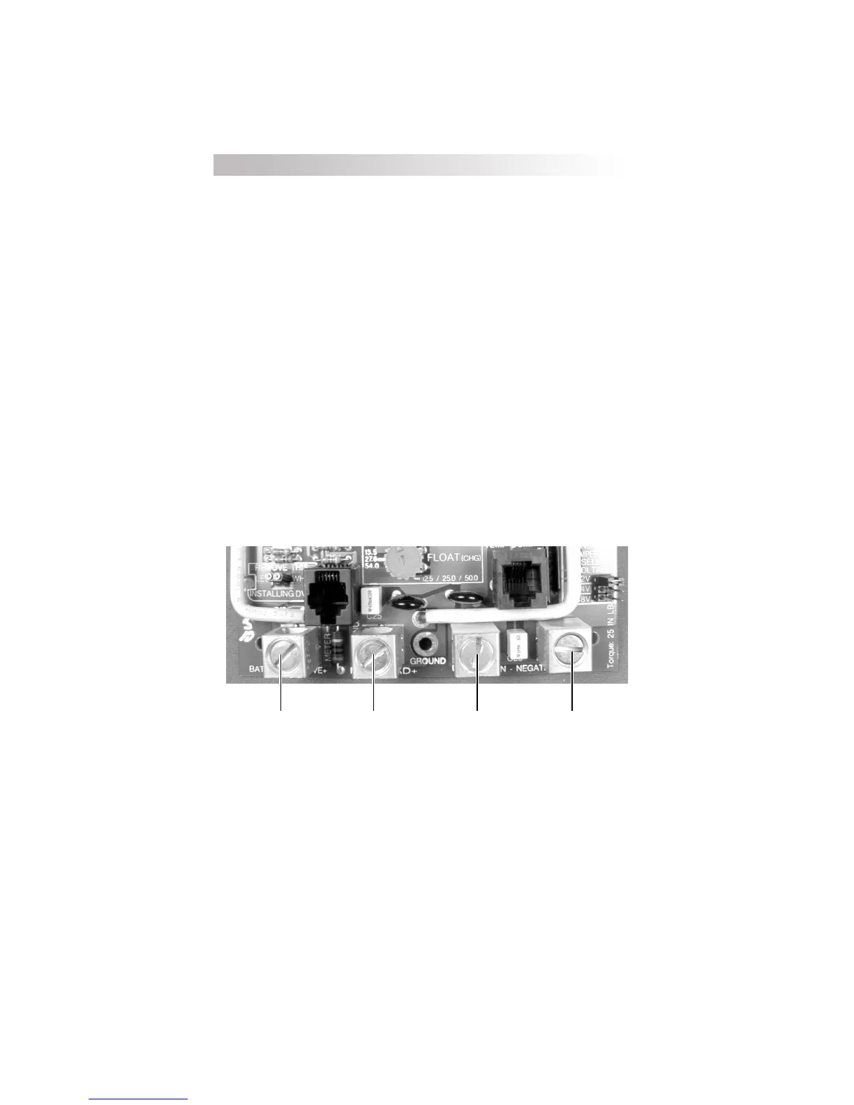
· Connect the PV arrays positive (+) output to the terminal marked PV POS/
LOAD at the bottom of C-Seriess circuit board and tighten the lugs.
· Connect the PV arrays negative () output to the terminal marked
COMMON NEGATIVES and tighten the lugs.
· Connect the battery positive (+) cable to the terminal marked BAT POS and
tighten the lugs.
· Connect the negative () battery cable to the terminal marked COMMON
NEGATIVES and tighten the lugs.
· Secure the cabling with strain reliefs after allowing a little slack inside the
case to prevent damage to the controllers circuit board.
Figure 5
PV Charge Control Mode Wiring
Battery Positive +
PV Array Positive +
Battery Negative PV Array Negative
16
3.0 INSTALLATION
 Loading...