8
© 2001 Xantrex Technology Inc.
P/N 973-0012-01-02 Rev. A 05/01
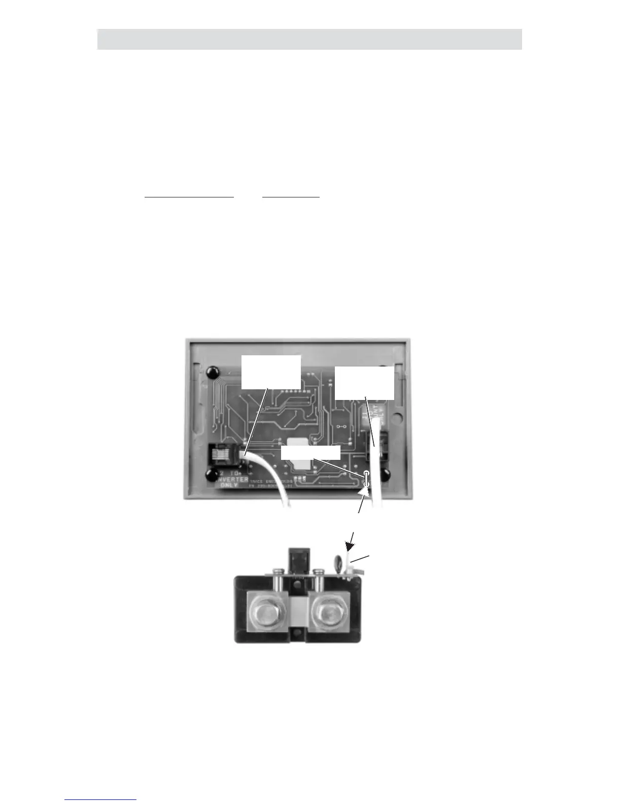
Extended Length Installations
If the TM500A is mounted in excess of 100 feet from the inverter, an
additional wire (with a spade lugs on both ends) must be connected between
the TM500A and shunt spade lugs. This wire acts as a ground reference and
ensures the meter will read accurately.
Use the following gauge wire for the distance the TM500A is mounted
from the inverter.
Maximum Distance Wire Gauge
250 feet #16 AWG
400 feet #14 AWG
630 feet #12 AWG
1000 feet #10 AWG
J2 TO
INVERTER
ONLY
J1 TO
SHUNT
ONLY
SPADE LUG
SPADE LUG
Interconnect for distances over
100 feet
Figure 2-6
Extended Length Ground Wire
2.0 INSTALLATION
 Loading...