Do you have a question about the Xantrex XKW 150-7 and is the answer not in the manual?
Details what the warranty covers and its duration.
Explains Xantrex's obligations for repair or replacement.
Provides contact information and steps to get service.
Lists conditions and damages not covered by the warranty.
States the sole and exclusive warranty provided by Xantrex.
Warns about specific limitations and intended uses of the product.
Explains the meaning of warning and caution symbols used in the manual.
Provides crucial safety instructions for operating the power supply.
Illustrates and explains the safety symbols used in the document.
Describes who should use the manual and its scope.
Outlines the main sections and content of the manual.
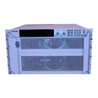
Provides a general overview of the power supply series.
Lists the main features and available options of the power supply.
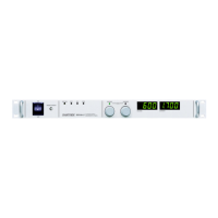
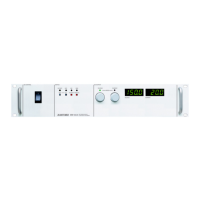
Details the controls and indicators found on the front of the unit.
Describes the connectors and switches located on the rear panel.
Provides a comprehensive look at all controls, connectors, and indicators.
Presents detailed electrical, environmental, and mechanical specifications.
Introduces the installation section and outlines the basic setup steps.
Guides on initial inspection, periodic cleaning, and packaging.
Details the process and policy for returning units to the manufacturer.
Provides instructions on how to pack the unit for shipping or storage.
Recommends suitable locations, mounting methods, and ventilation requirements.
Explains how to connect AC power and select the correct input voltage.
Discusses the impact of input line impedance on operation.
Outlines procedures for testing voltage and current modes.
Details how to verify voltage mode operation.
Details how to verify current mode operation.
Provides recommendations for connecting loads and conductor ratings.
Instructions for assembling and attaching the output cord strain relief.
Explains the use of local and remote sensing for regulation.
Guides on operating a single unit using front panel controls.
Covers operating units in series, parallel, or split configurations.
Explains how to connect units in series for higher voltage output.
Explains how to connect units in parallel for higher current output.
Describes obtaining dual positive or positive-negative outputs.
Details the OVP feature, its purpose, and activation.
Instructions for setting the OVP trip level via the front panel.
How to program OVP trip level using external voltage sources.
How to program OVP trip level using an external potentiometer.
How to program OVP trip level using an external current source.
How to shift OVP sense point from output to remote sense connections.
Explains how to control the output state remotely via TTL or AC/DC input.
Details using an external relay for remote ON/OFF control.
Overview of programming output voltage and current limits remotely.
How to program output voltage using 0-5V or 0-10V external sources.
How to program voltage/current limits using a 5k ohm potentiometer.
How to program voltage/current limits using a 0-1mA current source.
Information on reading back output status and indicators via J3 connector.
Explains the OTP feature and how the supply protects against overheating.
Procedures for resetting the OTP after a shutdown event.
Introduces calibration and provides critical safety warnings.
Details the procedures and precautions for setting up calibration.
Identifies trimpot locations and parameters for calibration adjustments.
| Brand | Xantrex |
|---|---|
| Model | XKW 150-7 |
| Category | Power Supply |
| Language | English |