EasyManua.ls Logo

Xantrex XDC 10-600 User Manual

Xantrex XDC 10-600
256 pages
To Next Page IconTo Next Page
Page #1 background imageLoading...
Page #1 background image
Artisan Technology Group is your source for quality
new and certied-used/pre-owned equipment
FAST SHIPPING AND
DELIVERY
TENS OF THOUSANDS OF
IN-STOCK ITEMS
EQUIPMENT DEMOS
HUNDREDS OF
MANUFACTURERS
SUPPORTED
LEASING/MONTHLY
RENTALS
ITAR CERTIFIED
SECURE ASSET SOLUTIONS
SERVICE CENTER REPAIRS
Experienced engineers and technicians on staff
at our full-service, in-house repair center
WE BUY USED EQUIPMENT
Sell your excess, underutilized, and idle used equipment
We also offer credit for buy-backs and trade-ins
www.artisantg.com/WeBuyEquipment
REMOTE INSPECTION
Remotely inspect equipment before purchasing with
our interactive website at www.instraview.com
LOOKING FOR MORE INFORMATION?
Visit us on the web at www.artisantg.com for more
information on price quotations, drivers, technical
specications, manuals, and documentation
Contact us: (888) 88-SOURCE | sales@artisantg.com | www.artisantg.com
SM
View
Instra

Table of Contents

Question and Answer IconNeed help?

Do you have a question about the Xantrex XDC 10-600 and is the answer not in the manual?

Xantrex XDC 10-600 Specifications

General IconGeneral
BrandXantrex
ModelXDC 10-600
CategoryPower Supply
LanguageEnglish

Summary

Limited Warranty

Warranty Coverage and Duration

Covers defects in workmanship and materials for 5 years from purchase date.

Xantrex's Responsibilities

Outlines Xantrex's options for repair or replacement and warranty continuation.

Obtaining Service

Provides instructions on contacting merchants or Xantrex for warranty service.

Warranty Disclaimer and Exclusions

Product Warranty Statement

States the warranty is the sole and exclusive warranty provided by Xantrex.

Warranty Limitations

Lists limitations and exclusions not covered by the limited warranty.

Power Supply Information

Warnings and Cautions

Power Supply Safety Precautions

Details safety measures for operating the power supply, including high voltage warnings.

IEC Symbols Used in Manual

Product Approvals

CE Mark Compliance

Lists standards met by CE-marked units, including IEC, EN, and EMC requirements.

CSA Certification

States CSA certification compliance with specific standards.

UL Listing Status

Indicates UL listing status and compliance with laboratory equipment safety standards.

FCC Compliance Statement

Confirms compliance with FCC Part 15 for radio frequency devices.

Canadian EMC Requirements

States compliance with Canadian EMC requirements.

About This Manual

Target Audience

Identifies the target audience for the manual based on their electrical knowledge.

Locating Information

Explains how to easily locate information within the manual using its structure.

Manual Sections Overview

Lists the main sections of the manual and provides brief descriptions.

Section 1. About The XDC Power Supply

Overview

General introduction to the XDC power supply series, its features, and applications.

Key Features

Details the key digital and analog features of the XDC power supply.

Front Panel Description

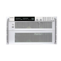
Describes the physical layout and components of the power supply's front panel.

Front Panel Display

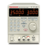
Explains the main display and status annunciators on the front panel.

Status Annunciators Explained

Lists and explains the meaning of the various status annunciators on the front panel display.

Rear Panel Layout

Details the connectors and ports located on the rear panel of the power supply.

Operation Overview

Explains the power supply's operation states and control modes.

Power ON Sequence

Describes the power-on sequence and default settings.

Control Mode Options

Details the available control modes: Local, RS-232, GPIB, Multichannel, and Analog.

Section 2. Installation

Installation Overview

Provides an overview of the recommendations and procedures for installing the power supply.

Basic Setup Procedure Summary

Summarizes the steps for setting up the power supply, referencing detailed sections.

Inspection, Cleaning, and Packaging

Returning Power Supplies to Manufacturer

Packaging for Shipping or Storage

Location, Mounting, and Ventilation

AC Input Power Connection

AC Input Wire Specifications

12000 W AC Wire Input Connection

Basic Checks and Self-Tests

Required Equipment

Lists the necessary equipment for performing basic checks and self-tests.

Display Test Procedure

Describes how to perform a display test to ensure proper functionality.

Power ON Sequence Check

Voltage Mode Operation Test

Current Mode Operation Test

Load Wiring Guidelines

Current Carrying Capacity

Explains the importance of wire capacity for load wiring and provides a rating table.

Load Wiring Length with Sense Lines

Noise and Impedance Effects Mitigation

Load Connections Procedure

Single Load Connection

Multiple Loads Connection

Output Strain Relief and Cover Installation

Remote Sensing Functionality

Section 3. Operation

Operation Overview

Introduces the operation section, covering power on/off and configuration procedures.

Powering ON the Power Supply

Provides step-by-step instructions for powering on the power supply and initial checks.

Power Supply Operating States

Power Supply Regulation Modes

Remote Control Modes

Front Panel Controls Overview

Front Panel Menu Navigation

Top Level Menu Items

Lists and describes the main menu options available on the power supply.

Front Panel Control Knobs

Power Supply Operation Procedures

Setting Output Voltage

Details the procedure for setting the DC voltage output setpoint via the front panel.

Setting Output Current

Details the procedure for setting the DC current output setpoint via the front panel.

Turning Output On or Off

Setting Output Protection Mechanisms

Fold Protection Configuration

Shutdown Recovery Configuration

Responding to Alarms

Setting Up Remote Control

Toggling Local/Remote Control

Describes how to switch between local (front panel) and remote control modes.

Selecting Remote Control Source

Storing User Settings

Changing Stored Settings

Recalling Settings

Selecting a Stored User Setting

Configuring Power ON Settings

Factory Preset Power-On Configuration

Configuring User Lines

Auto-Sequence Operations

Program Auto Sequence

Guides the user through programming automated sequences with multiple steps.

Sequence Programming Procedure

Setting Sequence Step Advance by Time

Setting Sequence Step Advance by Trigger

Deleting a Sequence

Editing a Sequence Step

Inserting a Sequence Step

Deleting a Sequence Step

Editing Sequence Repeat Times

Editing Sequence Trigger Source

Using Auto Sequencing

Configuring Display Settings

Locking Out Control Knobs

Setting Voltage, Current, and Power Limits

Setting Current Limits

Setting Power Limit

Slew Rate Control

Setting Slew Rate Parameters

View Model Information

Default Display Configuration

Viewing Power Output

Describes how to view the present power output in watts.

Monitoring Status Indicators

Refers to front panel indicators and annunciators for monitoring status.

Section 4. Remote Operation

Remote Operation Overview

Introduces the remote operation capabilities, including available interfaces and command formats.

Remote Interface Connections

Remote Analog Operation

Analog Control Configuration

Guides users on configuring the analog programming lines for voltage and current control.

SCPI Commands for Analog Control

Multichannel Operation (6000 Watt only)

Multichannel Connections

Describes the physical connections for multichannel operation, including CANbus.

Multichannel Configuration

Multichannel Setup

Using Multichannel Operation

Multichannel Commands

RS-232 Operation

RS-232 Configuration

RS-232 SCPI Commands

Lists SCPI commands for RS-232 configuration, including baud rate and flow control.

Using RS-232

Describes how to use the RS-232 interface for remote control and mode switching.

GPIB Operation

GPIB Configuration

Explains how to set the GPIB address and power-on service request settings.

GPIB SCPI Commands

Lists SCPI commands for GPIB control parameters and configuration.

Using GPIB

Describes how to send GPIB commands and manage remote/local modes.

SCPI Commands for Digital Interfaces

Power On Configuration Commands

Covers SCPI commands for Factory Preset, Last Setting, User Settings, and Auto Sequence.

Remote Control and Output Commands

Includes SCPI for changing remote/local modes, enabling output, and programming V, I, P.

Protection Configuration Commands

Details SCPI commands for setting voltage, current, power, temperature, and AC off protections.

Sequence and Triggering Commands

Covers SCPI commands for programming, editing, and executing auto sequences and triggers.

Status and Error Commands

Includes SCPI commands for reading and clearing error messages and querying status registers.

Section 5. Current Sharing (6000 Watt only)

Current Sharing Overview

Introduces the current sharing function, its availability, and requirements for 6000 Watt units.

Current Sharing Theory of Operation

Explains how power supplies connected in parallel share current to deliver a larger output.

Current Sharing Operation

Describes how to operate the power supply when configured for current sharing, including master/slave roles.

Current Sharing Errors

Lists and explains potential errors encountered during current sharing operation.

Current Sharing Specifications

Provides specifications related to current sharing, such as connected units and cable length.

Appendix A. Calibration

Calibration Overview

Introduces the calibration procedures, noting software dependency and available methods.

Entering Calibration Mode

Details how to enter calibration mode via front panel or SCPI commands, including security codes.

Restore Factory Calibration

Explains how to restore the unit to its factory calibration constants.

Appendix B. SCPI Command Reference

SCPI Reference Overview

Provides a summary of Standard Commands for Programmable Instruments (SCPI) supported by the power supply.

SCPI Codes and Standards

Lists the international standards to which the power supply conforms.

SCPI Syntax and Style

Describes the syntax rules, parameters, and hierarchy of SCPI commands.

SCPI Command Hierarchy

Explains the structure of SCPI commands as organized around roots and nodes.

SCPI Command Summary

Provides a summary of supported SCPI commands with their function, description, and query capability.

Appendix C. Error Messages

Error Messages Overview

Explains how errors are queued and cleared according to IEEE 488.2 standards.

Command Error List

Lists and describes errors related to IEEE 488.2 syntax errors detected by the instrument's parser.

Execution Error List

Lists and describes errors detected by the instrument's execution control block after rounding and evaluation.

Device-Specific Error List

Query Error List

User Request Event Errors

Operation Complete Event Errors

CANbus Error Codes

Multichannel Error Codes

Current Share Error Codes

Appendix D. GPIB Interface

GPIB Overview

Introduces the GPIB interface for programming the power supply remotely.

GPIB Codes and Standards

GPIB Message Terminators

GPIB Address Range

GPIB Service Request and Polling

GPIB Protocol Specifications

GPIB Electrical Specifications

GPIB Performance Specifications

Appendix E. Specifications and Characteristics

General Specifications Notes

General notes regarding the specifications provided in this appendix.

Electrical Specifications Summary

6000W (10V-60V) Drift Specs

6000W (80V-600V) Specs

6000W (80V-600V) Drift Specs

12000W (10V-60V) Specs

12000W (10V-60V) Drift Specs

12000W (80V-600V) Specs

12000W (80V-600V) Drift Specs

AC Line Input Specifications

Output Performance Specifications

Rated Output Range

Defines the voltage and current ranges for the power supply output.

Efficiency

Provides typical and minimum efficiency ratings for the power supply.

Load Regulation

Specifies load regulation for voltage and current under varying load conditions.

Line Regulation

Specifies line regulation for voltage and current under varying input voltage.

Programming Range for V, I, P

Defines the programmable range for voltage, current, and power output.

OVP Programming Range

Specifies the programmable range for Over-Voltage Protection.

Typical Programming Resolution

Typical Measurement Resolution

Programming Accuracy

Readback Accuracy

30 Minute Drift

8 Hour Drift and Temp Stability

Temperature Coefficients

Analog Programming Interface

User Line Interface

Switching Frequency

Rise Time

Fall Time

Power-On to Output Stable Delay

Output Enable to Output Stable Delay

Output Hold-Up Time – Power Off

Output Hold-Up Time – Source Interruption

Transient Response Time

Mode Crossover

Noise Bandwidth Limits

Remote Sense Line Drop Compensation

Isolation Specifications

Environmental Specification

Thermal Specification

Details operating and storage temperature ranges, and altitude limitations.

Humidity Specification

Specifies the operating and storage humidity ranges.

International Approvals

Lists the international certifications and standards met by the product.

Mechanical Specification

Physical Dimensions (Size)

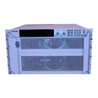
Provides physical dimensions and weight specifications for the power supply units.

Related product manuals