Release 3.0 xix
List of Figures
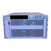
Figure 1.1 Front Panel (6000 Watt) . . . . . . . . . . . . . . . . . . . . . . . . . . . . . . . . . . . 22
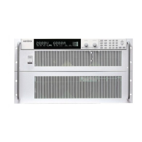
Figure 1.2 Front Panel (12000 Watt) . . . . . . . . . . . . . . . . . . . . . . . . . . . . . . . . . . 23
Figure 1.3 Keypad . . . . . . . . . . . . . . . . . . . . . . . . . . . . . . . . . . . . . . . . . . . . . . . . 24
Figure 1.4 Front Panel Display . . . . . . . . . . . . . . . . . . . . . . . . . . . . . . . . . . . . . . . 28
Figure 1.5 Front Panel Display, Status Annunciators . . . . . . . . . . . . . . . . . . . . . . 28
Figure 1.6 Rear Panel (6000 Watt low and medium output shown) . . . . . . . . . . . 30
Figure 2.1 Typical Box Label for Storage . . . . . . . . . . . . . . . . . . . . . . . . . . . . . . . 36
Figure 2.2 Unpacking the Power Supply (6000 Watt shown) . . . . . . . . . . . . . . . . 38
Figure 2.3 Mounting the Power Supply in the Rack With Support Rails . . . . . . . . 39
Figure 2.4 AC Input Connector for 6000 Watt units . . . . . . . . . . . . . . . . . . . . . . . 40
Figure 2.5 Attaching the AC Input Wires for 6000 Watt units . . . . . . . . . . . . . . . . 42
Figure 2.6 Attaching the AC Input Wires for 12000 Watt units . . . . . . . . . . . . . . . 44
Figure 2.7 Fastening the Output Wires (6000 Watt) . . . . . . . . . . . . . . . . . . . . . . . 52
Figure 2.8 Output Bus Bar Cover for 6000 Watt units . . . . . . . . . . . . . . . . . . . . . 53
Figure 2.9 Output for 12000 Watt units (Low and Medium Voltage). . . . . . . . . . . 53
Figure 2.10 Output Cover with Strain Relief for 6000 Watt units . . . . . . . . . . . . . . 54
Figure 2.11 Output for 12000 Watt units (High Voltage 300–600V) . . . . . . . . . . . . 55
Figure 4.1 View of Remote Interface Connections . . . . . . . . . . . . . . . . . . . . . . . 107
Figure 4.2 Schematic For User Line Interface . . . . . . . . . . . . . . . . . . . . . . . . . . 109
Figure 4.3 Connections for Multichannel Operation . . . . . . . . . . . . . . . . . . . . . . 115
Figure 4.4 Operation Status Registers . . . . . . . . . . . . . . . . . . . . . . . . . . . . . . . . 144
Figure 4.5 Questionable Status Registers . . . . . . . . . . . . . . . . . . . . . . . . . . . . . 150
Figure 4.6 IEEE 488.2 Status Register and Status Byte. . . . . . . . . . . . . . . . . . . 153
Figure 5.1 Connections for Current Share Operation . . . . . . . . . . . . . . . . . . . . . 173
Figure E.1 Power Supply Dimensions (6000 Watt unit) . . . . . . . . . . . . . . . . . . . 243
Figure E.2 Power Supply Dimensions (12000 Watt unit) . . . . . . . . . . . . . . . . . . 244
Artisan Technology Group - Quality Instrumentation ... Guaranteed | (888) 88-SOURCE | www.artisantg.com
 Loading...