Do you have a question about the Xantrex XDC 60-100 and is the answer not in the manual?
Remotely inspect equipment before purchasing with our interactive website.
Covers defects in workmanship and materials for 5 years from date of purchase.
Xantrex will repair or replace defective product free of charge.
Contact your merchant or Xantrex directly for troubleshooting or service.
Excludes normal wear and tear, misuse, neglect, improper installation, or unauthorized repairs.
Federal law does not allow exclusion of implied warranties for consumer products.
Contains important safety warnings about high energy, high voltage, and proper operating environment.
CE-marked units meet IEC, EN standards for emissions and immunity.
CSA C22.2 No. 1010.1-92.
Meets UL3101-1 for laboratory electrical equipment.
FCC Part 15 - Radio Frequency Devices - Class A Limits.
Complies with Canadian EMC requirements of ICES-001.
For users understanding basic electrical theory and power supply operation.
Lists Table of Contents, Figures, Tables, and Index for easy information locating.
Outlines the manual's sections covering power supply, installation, operation, and calibration.
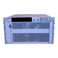
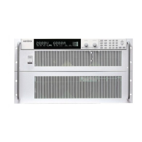
Introduces the XDC Series DC power supplies and their digital technology.
Lists key features like digital processing, auto sequences, stored settings, and soft switching.
Describes the front panel layout, controls, and display for user interaction.
Details the main display and status annunciators for monitoring supply status.
Explains the meaning of various status indicators on the front panel display.
Illustrates and describes the connectors and ports located on the rear panel.
Explains the power-on sequence and states of the power supply.
Describes the power-on procedure and initial default settings.
Lists and describes the available control modes: Local, RS-232, GPIB, Multichannel, and Analog.
Provides recommendations for inspecting, installing, and testing the power supply.
Summarizes the setup steps, referring to detailed sections for each.
Explains how to power the supply on/off, configure it, and use front panel controls.
Details the procedure for turning the power supply on.
Describes the five operating states: Power-On, Output Shutdown, Soft Start, Normal Operation, and Calibration.
Explains Constant Voltage (CV), Constant Current (CC), and Constant Power (CP) modes.
Details the feature allowing automatic switching between regulation modes based on load changes.
Lists and describes remote control interfaces like Analog, RS-232, GPIB, and Multichannel.
Describes the function keys, menu navigation, and control knobs for front panel operation.
Introduces remote operation via Analog, RS-232, GPIB, and Multichannel interfaces.
Shows how to connect interfaces like RS-232, GPIB, CANbus, and Analog programming lines.
Details using analog programming interfaces for voltage and current control.
Explains the function and power flow of pins on user and analog programming ports.
Guides on configuring analog programming lines for 0-5V or 0-10V ranges and control options.
Provides a summary of SCPI commands supported by the power supply.
Lists international standards the supply conforms to, including IEEE and SCPI.
States that GPIB control implements all IEEE 488.2 requirements.
Lists SCPI requirements the supply conforms to, including status registers.
Explains programming via GPIB interface, meeting IEEE 488.2 and SCPI standards.
Details GPIB interface implementation according to IEEE standards.
Describes GPIB message terminators like EOI and LF.
Specifies the GPIB address range the supply responds to.
Explains GPIB serial poll responses and SRQ generation.
Summarizes electrical specifications for 6000 Watt units across various models.
Explains connecting multiple supplies via CANbus for multichannel operation.
Describes the CANbus port and its role in multichannel and current sharing.
Details configuring each supply with a unique address for multichannel operation.
Guides on connecting supplies and setting up the CANbus network for multichannel operation.
Describes connecting the power supply via a standard null modem cable to a host.
Guides on setting RS-232 parameters like baud rate and flow control.
Describes the GPIB port and its pin functions.
Details setting GPIB address and power-on service request settings.
Explains SCPI commands to set power-on defaults: Factory Preset, Last Setting, User Settings, Auto Sequence.
Explains current sharing function for 6000 Watt units using CANbus interface.
Describes how parallel power supplies equalize current draw via master/slave adjustments.
Details configuring current sharing via SCPI or Front Panel (No sharing, Master, Slave).
Explains front panel setup for current share mode and display of summed current.
Lists potential errors and conditions that disable current sharing or cause slave/master issues.
Outlines calibration procedures for 6000 W units, software-dependent, automated.
Explains how to enter calibration mode via front panel or SCPI commands.
Describes using MIN and MAX as alternative choices for parameter values.
Explains using a question mark to query parameter values.
Details the required terminating characters for SCPI command strings.
Lists IEEE 488.2 common commands starting with an asterisk.
Defines units of measure and supported optional multipliers for SCPI parameters.
Explains the hierarchical structure of SCPI commands with an example.
Defines Boolean parameters as binary conditions like ON/OFF or 1/0.
Explains discrete parameters for settings with limited values, responding in short uppercase form.
Describes numeric parameters including decimal points, signs, and engineering units.
Defines string parameters requiring ASCII characters enclosed in quotes.
Provides tables of SCPI commands with function, command, description, and query support.
Lists abbreviations used in SCPI command tables, like N/A.
Explains how errors are queued (FIFO), cleared, and classified (SCPI standard vs. supply-specific).
Lists IEEE 488.2 syntax errors detected by the parser, setting the command error bit.
Lists errors detected by the execution control block after rounding and evaluation, setting the execution error bit.
Specifies driver types for interface lines and their specifications.
Lists operating and storage temperature ranges and altitude limits.
Specifies operating and storage humidity ranges.
Lists CE, CSA, FCC, and Canadian EMC approvals.
Provides dimensions for the 6000 Watt power supply unit.
| Brand | Xantrex |
|---|---|
| Model | XDC 60-100 |
| Category | Power Supply |
| Language | English |