EasyManua.ls Logo

Xantrex XDC 40-150 User Manual

Xantrex XDC 40-150
256 pages
To Next Page IconTo Next Page
Page #1 background imageLoading...
Page #1 background image
Artisan Technology Group is your source for quality
new and certied-used/pre-owned equipment
• FAST SHIPPING AND
DELIVERY
• TENS OF THOUSANDS OF
IN-STOCK ITEMS
• EQUIPMENT DEMOS
• HUNDREDS OF
MANUFACTURERS
SUPPORTED
• LEASING/MONTHLY
RENTALS
• ITAR CERTIFIED
SECURE ASSET SOLUTIONS
SERVICE CENTER REPAIRS
Experienced engineers and technicians on staff
at our full-service, in-house repair center
WE BUY USED EQUIPMENT
Sell your excess, underutilized, and idle used equipment
We also offer credit for buy-backs and trade-ins
www.artisantg.com/WeBuyEquipment
REMOTE INSPECTION
Remotely inspect equipment before purchasing with
our interactive website at www.instraview.com
LOOKING FOR MORE INFORMATION?
Visit us on the web at www.artisantg.com for more
information on price quotations, drivers, technical
specications, manuals, and documentation
Contact us: (888) 88-SOURCE | sales@artisantg.com | www.artisantg.com
SM
View
Instra

Table of Contents

Question and Answer IconNeed help?

Do you have a question about the Xantrex XDC 40-150 and is the answer not in the manual?

Xantrex XDC 40-150 Specifications

General IconGeneral
DC Output Current40 A
Output Power6000 W
Output Current40 A
Power6000 W
CoolingForced air

Summary

Limited Warranty

What does this warranty cover and how long does it last?

Explains warranty coverage and duration.

How do you get service?

Provides instructions on how to obtain warranty service and contact information.

Disclaimer Product

Warranty Exclusions

Details warranty exclusions and consumer legal rights.

Information About Your Power Supply

Warnings and Cautions

Power Supply Safety Precautions

Details safety precautions for using the power supply, including high voltage.

IEC Symbols Used in This Manual

Approvals

About This Manual

Manual Navigation and Structure

Explains how to navigate and understand the manual's organization.

Section 1: About the XDC Power Supply

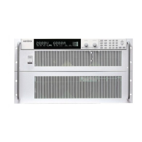
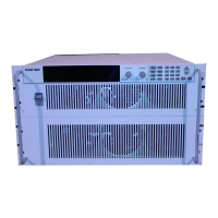
Describes the power supply features, front panel controls, display, and rear panel connectors.

Appendix B: SCPI Command Reference

Appendix C: Error Messages

Appendix E: Specifications and Characteristics

Section 1. About The XDC Power Supply

Features

Lists the key features and capabilities of the XDC Power Supply.

Front Panel Overview

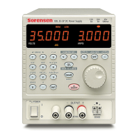
Details the components and layout of the power supply's front panel.

Rear Panel Overview

Details the connectors and ports located on the rear panel.

Section 2. Installation

Basic Setup Procedure

Outlines the fundamental steps for setting up the power supply.

Section 3. Operation

Powering ON the Power Supply

Step-by-step guide on how to power on the power supply.

Normal Operation

Defines the standard operating state of the unit.

Calibration

Outlines the service mode for calibrating setpoints.

Power Supply Regulation Modes

Constant Voltage (CV)

Details operation in Constant Voltage mode.

Constant Current (CC)

Details operation in Constant Current mode.

Automatic Mode Crossover

Describes the automatic switching between regulation modes.

Remote Control Modes

Front Panel Controls

Function Keys

Details the functionality of the eight function keys on the front panel.

Control Knobs

Describes the voltage and current control knobs and their operation.

Basic Checks or Self-Tests

Display Test

Instructions for verifying the functionality of the front panel display.

Voltage Mode Operation Check

Current Mode Operation Check

Load Wiring

Current Carrying Capacity

Details wire gauge requirements based on current carrying capacity.

Load Connections

Isolation Requirements

Requirements for wire insulation for output connections.

Single Load Connection

Multiple Loads Connection

Remote Sensing Functionality

Powering ON the Power Supply

Power Supply Operating States

Normal Operation

Defines the standard operating state of the unit.

Power Supply Regulation Modes

Constant Power (CP)

Details operation in Constant Power mode.

Front Panel Controls

Menu Navigation

Explains how to navigate through the menu system using the keys.

Top Level Menu Items

Lists the primary menu options available for configuration.

Power Supply Operation

Set Voltage

Procedure for setting the DC voltage output setpoint.

Set Current

Procedure for setting the DC current output setpoint.

Power Supply Operation

Turn Output On or Off

How to enable or disable the power supply's output.

Set Output Protection

Explains the seven configurable protection mechanisms.

Toggle Local/Remote Control

Select Remote Control Source

Store User Settings

Saving User Settings

Step-by-step guide to saving current settings.

Recall Settings

Read Error Messages

Configure Power ON Settings

Factory Preset Power-On

Restores factory default settings upon power-on.

Auto-Sequence Operation

Selecting an Auto Sequence

Steps to select an auto-sequence program for execution.

Configure Display Settings

Lock Out Control Knobs

Set Voltage, Current, and Power Limits

Voltage Limits

Procedure for setting the upper and lower voltage limits.

Slew Rate Control

Setting the Slew Rate

Step-by-step procedure to adjust the voltage slew rate.

View Model Information

Default Display Configuration

Section 4. Remote Operation

Overview

Introduces the remote operation section and its main parts.

Making Connections for Remote Control

Remote Analog Operation

Analog Connections

Describes the analog interface ports and pin functions.

Analog Programming Interface 0-10V Range

Remote Interface Calibration Procedure

Output Voltage Calibration

Calibration steps for output voltage using SCPI.

Output Current Calibration

Calibration steps for output current using SCPI.

Exit Calibration Mode

Restore Factory Calibration

Appendix B: SCPI Command Reference

Overview

Introduces the SCPI command reference.

Codes and Standards

Lists standards the power supply conforms to.

IEEE-488.2/SCPI Syntax and Style

SCPI Command Hierarchy

Describes the structure and organization of SCPI commands.

Using SCPI Commands

SCPI Command Summary

Appendix C: Error Messages

Command Error List

Details IEEE 488.2 syntax and command errors.

Execution Error List

Lists errors detected during the execution of commands.

Device-Specific Error List

Query Error List

Front Panel Error Codes

Auto Sequencing Error Codes

CANbus Error Codes

Current Share Error Codes

Appendix D. GPIB

Overview

Introduces the GPIB appendix.

Address Range

Details the primary and secondary GPIB address ranges.

Electrical Specifications

Driver Requirements

Details the requirements for GPIB interface drivers.

Performance Specifications

Appendix E. Specifications and Characteristics

Electrical Specifications—Summary

Summarizes the key electrical specifications for 6000 Watt units.

Programming Accuracy

Details the accuracy of programming voltage, current, and power.

Readback Accuracy

Details the accuracy of voltage, current, and power readback.

AC Line Input Specifications

AC Line Input Voltage Operating Ranges

Specifies the voltage ranges for standard and HV-input options.

Output Performance Specifications

Rated Output Range

Specifies the output voltage and current ranges.

Load Regulation

Details regulation performance under varying load conditions.

Line Regulation

Details regulation performance with varying input voltage.

Output Performance Specifications

30 Minute Drift

Specifies output drift over 30 minutes.

Temperature Coefficients

Details how output varies with temperature changes.

Output Performance Specifications

Rise Time

Specifies the time for output voltage to rise from 5% to 95%.

Output Hold-Up Time – Power Off

Minimum time the output remains stable after power loss.

Transient Response Time

Time to recover output voltage after a load current step change.

Environmental Specification

Thermal Specification

Specifies operating and storage temperature ranges.

International Approvals

Lists product certifications and compliance standards.

Mechanical Specification

Size and Dimensions

Illustrates the physical dimensions of the power supply.

Related product manuals