XFP 16 ZONE ANALOGUE ADDRESSABLE FIRE ALARM PANEL
XFP ENGINEERING MANUAL • Approved Document No. DFU1200510 Rev 3 • Page 9 of 36
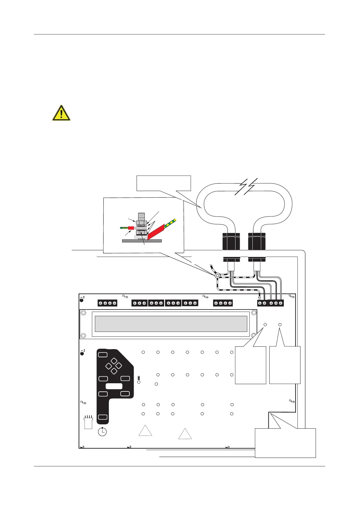
Connecting the analogue loop to the Main Control PCB
The analogue loop should be connected to the Main Control PCB as illustrated in Fig. 5 below.
Remember to isolate the panel’s Mains and battery backup supplies before making any connections.
The loop’s earth screens should be adequately insulated and connected between the nut and washers on
the base earth distribution post using eyed crimp connectors. Do not disturb the lower nut - this must
be secure to ensure earth continuity.
The base earth distribution post is provided for terminating earth screens or drains and is NOT the
main earthing point. The installer must review the external earth bonding (if required) with
respect to the national wiring rules. If the installation requires protective earth bonding, then this
must be applied externally and in conjunction with the type of earthing system employed on site.
Note that the Main Control PCB connects to the Power Supply PCB via an 8-way telecoms-style connector
cable, the socket for which is located on the PCB’s reverse. This cable must be connected before the Main
Control PCB is secured in the panel. Ensure all six PCB retaining screws are properly tightened before oper-
ation as they play an important part in the electrical safety and EMC immunity of the panel.
Fig. 5 : Typical analogue addressable loop connection
TO THE MANUFACTURERS INSTRUCTIONS.
 Loading...