Do you have a question about the XFP XFP501E/X and is the answer not in the manual?
Lists components included in the panel package.
Discusses general fire alarm system design and client consultation.
Details recommended cable types and their limitations for installation.
Provides essential precautions for handling static-sensitive components.
Details the panel enclosure and procedure for removing internal PCBs.
Guides on wall mounting and planning internal cable layout.
Specifies requirements for mains supply wiring and connection.
Step-by-step instructions for connecting mains power to the PSU PCB.
Discusses factors affecting loop design, resistance, and capacity for reliability.
Instructions for connecting the analogue loop to the main control PCB.
Illustrates typical network wiring configurations for main panels and repeaters.
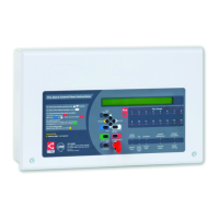
Describes the front panel layout, controls, and the function of various LEDs.
Explains the operation of the panel's buttons and keyswitch for user interaction.
Outlines the steps and factors for effective system commissioning.
Defines terms like Zone, Group, and Set for system operation.
Presents a hierarchical overview of panel menu options and access levels.
Details the methods for accessing the panel's highest operational level.
Explains the purpose and use of the NVM memory unlock link for site-specific changes.
Covers viewing fire events, fault events, disablements, and zones in test.
Describes changing access codes and establishing PC connection for programming.
Introduces commissioning tasks like loop learn, finding devices, and showing fitted devices.
Details assigning devices to zones/groups and calibrating devices.
Covers configuring day/night modes and automatic Daylight Saving Time adjustments.
Allows global or individual disabling/enabling of sounder groups.
Options for resetting the system and enabling/disabling zones, outputs, and devices.
Procedures for testing individual device outputs and system output sets.
Covers testing sounder groups and the panel's volt-free relays.
Methods for performing walk tests and using LED blinking to locate faults.
Monitors specific devices by repeated polling to diagnose loop faults.
Performs loop tests to identify wiring faults and displays device database information.
Displays firmware version, site data, and power supply unit status.
Options to enable/disable earth fault monitoring and view loop current levels.
Accesses device EEPROM data and views network event status for fault diagnosis.
| Number of Loops | 1 |
|---|---|
| Number of Sounder Circuits | 2 |
| Enclosure Material | Metal |
| Display Type | LCD |
| Protection Rating | IP30 |
| Operating Temperature | 40°C |