61
Factory
default value
PID reference
feedback range
F9.01
1000
Setup range
0 9999~
PID reference feedback range is a nondimensional unit , it is used
to display the PID reference and feedback .
F9.02
PID digital reference
500
Factory
default value
0 F9.01~
Setup range
PID digital reference is one of the PID reference channel. Refer
to explanation about the second expression mode of PID
reference for its meaning.
PID second digital
reference
Factory
default value
F9.03
500
0 F9.01~
Setup range
PID second digital reference is one of the PID reference channel.
Refer to explanation about the second expression mode of PID
reference for its meaning.
PID second digital reference is a default PID
reference source .
makeup of the
The external terminal is set as 25 by Group F3 parameter ,when
the terminal enabled ,PID setup value will be switched from
the first part of
F9.00 into the F9.03.
PID reference channel value selected in the
value of
F9.04
0.0%
Deviation limit
0.0 50.0%~
0
Reserved function
F9.05
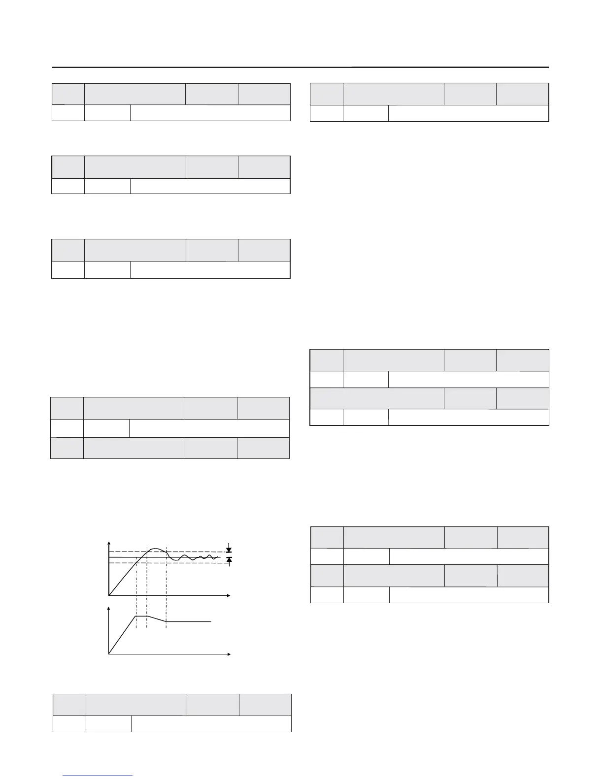
Deviation limit It means that PID system output value corresponding
to the loop reference. When the PID
feedback deviation is within this range , the PID stops adjustment . It is
shown as the follows . Setting the function code in reason can improve
the precision and stability of PID system .
:
biggest deviation allowed by close
Feedback quantity
Reference
Deviation limit
Time
Output frequency
Setup range
Factory
default value
Factory
default value
Chapter 6 Parameter Description
Time
Fig.6-18 Corresponding Relationship between Deviation
Limit and Output Frequency
Factory
default value
20.0%
Proportional gain P
F9.06
Setup range
0 100.0% 0.0% : close P~
2.0S
Factory
default value
Integration time I
F9.07
Setup range
0.1 100.0s 100.0s : close I~
Proportional gain P:
It decides the adjustment intensity of the whole PID regulator . The
higher the P is , the more powerful the adjustment intensity is .
When this parameter is 100 , it indicates the deviation between
PID feedback quantity and the reference quantity is 100% ,
the adjustment amplitude appointed by
the output frequency as the maximum frequency (the integral and
differential functions are neglected) .
the
PID regulator regards
Integration time I:
It decides the speed of PID regulator adjusting the deviation
between the PID feedback quantity and the reference quantity .
Integration time is the time within which the integration regulator
(the proportional and differential functions are neglected) performs
continuous adjustment and the adjustment quantity reaches the
maximum frequency when the deviation between the PID feedback
quantity and reference quantity is 100% .The shorter the integration
time is, the more powerful the adjustment intensity is .
Factory
default value
F9.08
0.0s
Differential time D
Setup range
0.0 10.00s~ 0.0s : close D
5.0%
Differential amplitude
F9.09
Factory
default value
Setup range
0.0 100.0%~
Differential time D:
It decides the intensity of PID regulator adjusting the change rate
of deviation between the PID feedback quantity and the reference
quantity .Differential time is the time within which if the feedback
quantity changes 100% , the adjustment quantity reaches the
maximum frequency (proportional and integral functions are
neglected) . The longer the differential time is , the more powerful
the adjustment intensity is .
In some applications, if process adjustment is set by optimum ,it will
delay the time to reach the required process state .In this kind of
application, you'd better make sure the output frequency that the
inverter inquired the motor to reach before start the process adjustment.
It can be setting parameter F9.10. In this operational mode,
if running command is , the inverter will according
to the acceleration/deceleration time at the open loop . Only when the
output frequency reached the setup PID preset frequency and it kept
running for a period of time, it run in term of
the close loop .(The PID preset frequency could set by
corresponding frequency of normally run of speed. This could be more
easy to meet the process condition).
realized by
input make response
at the frequency point will
characteristics of
0.00Hz
0.0s
0.0Hz the maximum frequency~
Factory
default value
Factory
default value
0.0 3600.0S~
PID preset frequency
PID preset frequency
keep time
Setup range
Setup range
F9.10
F9.11
 Loading...