124 Xilinx Development System
Xilinx System Generator v2.1 Reference Guide
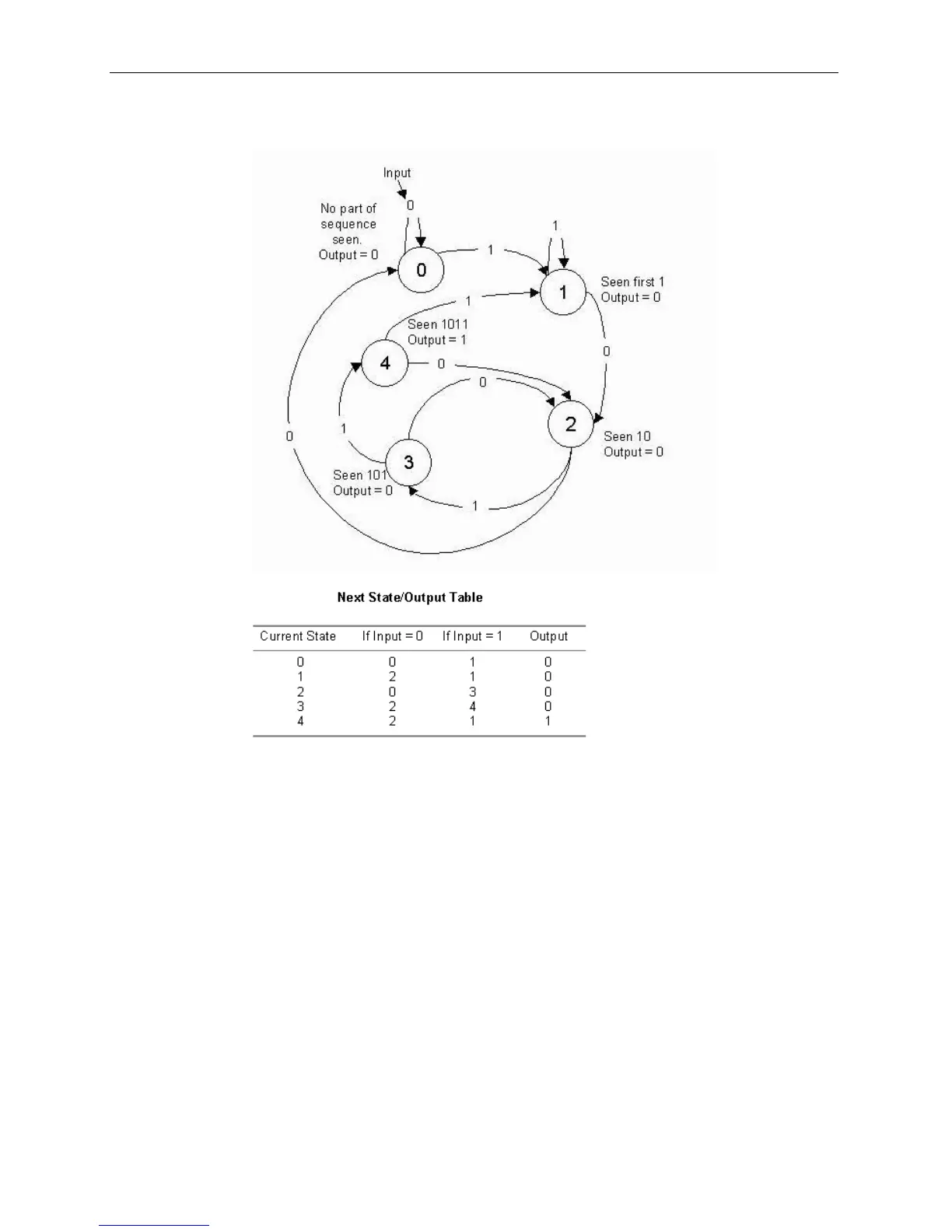
stream of bits. The state transition diagram and next state/output table are shown
below.
Figure 3-89: Registered Moore State Machine example transition diagram and
table
The table lists the next state and output that result from the current state and input.
For example, if the current state is 4, the output is 1 indicating the detection of the
desired sequence, and if the input is 1 the next state is state 1.