State Machine 125
Xilinx Blocks
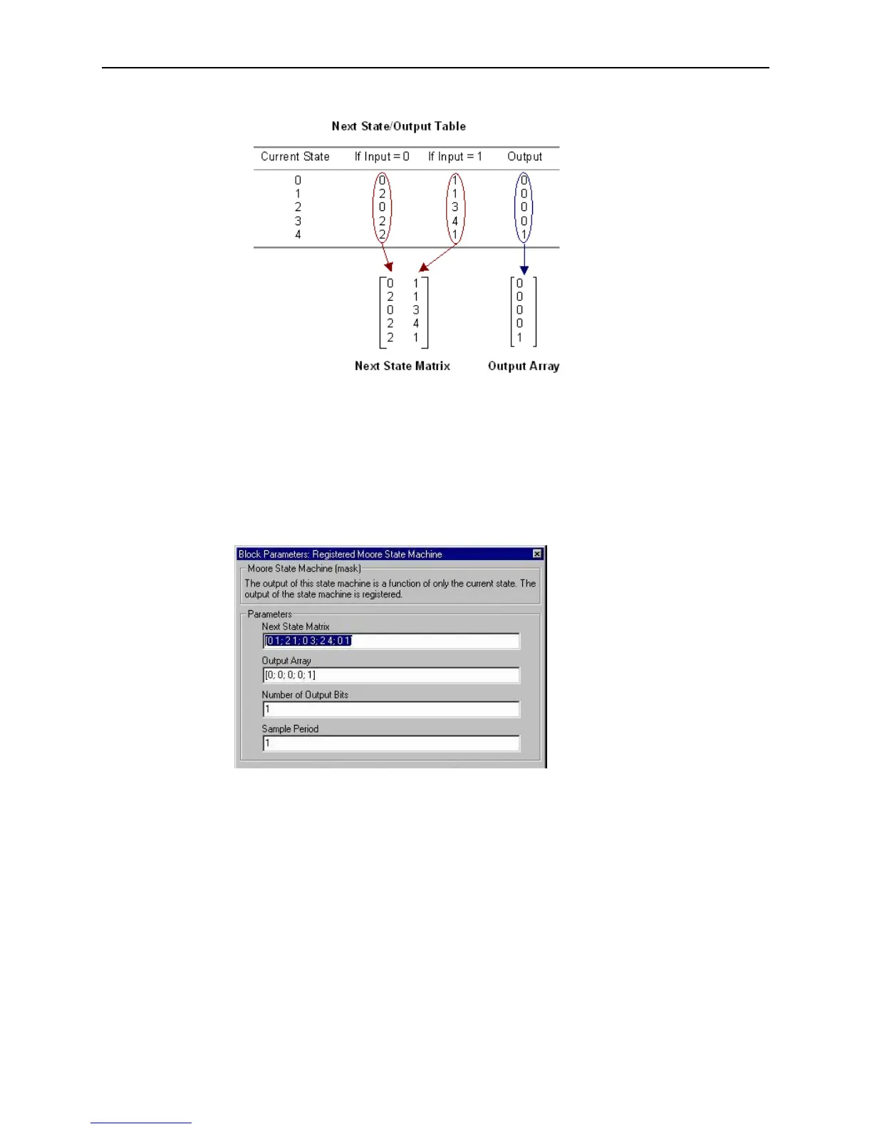
The Next State Matrix and the Output Array are composed in the following way:
Figure 3-90: Construction of Next State and Output matrices
The rows of the matrices correspond to the current state. The next state matrix has
one columns for each input value. The output array has only one column since the
input value does not affect the output of the state machine.
Block Parameters Dialog Box
The block parameters dialog can be invoked by double-clicking the icon in your
Simulink model:
Figure 3-91: Registered Moore State Machine block parameters dialog box
The next state logic, state register, is implemented using the Xilinx Block RAM
LogiCORE. A separate Block RAM LogiCORE is used to implement the output logic
and output register.
The number of bits used to implement the state logic and state register is given by the
equations:
d
s
2
k
()2
i
() 2
ki+
==
w
s
k=
N
s
d
s
w
s
× k()2
ki+
()==