48 Xilinx Development System
Xilinx System Generator v2.1 Reference Guide
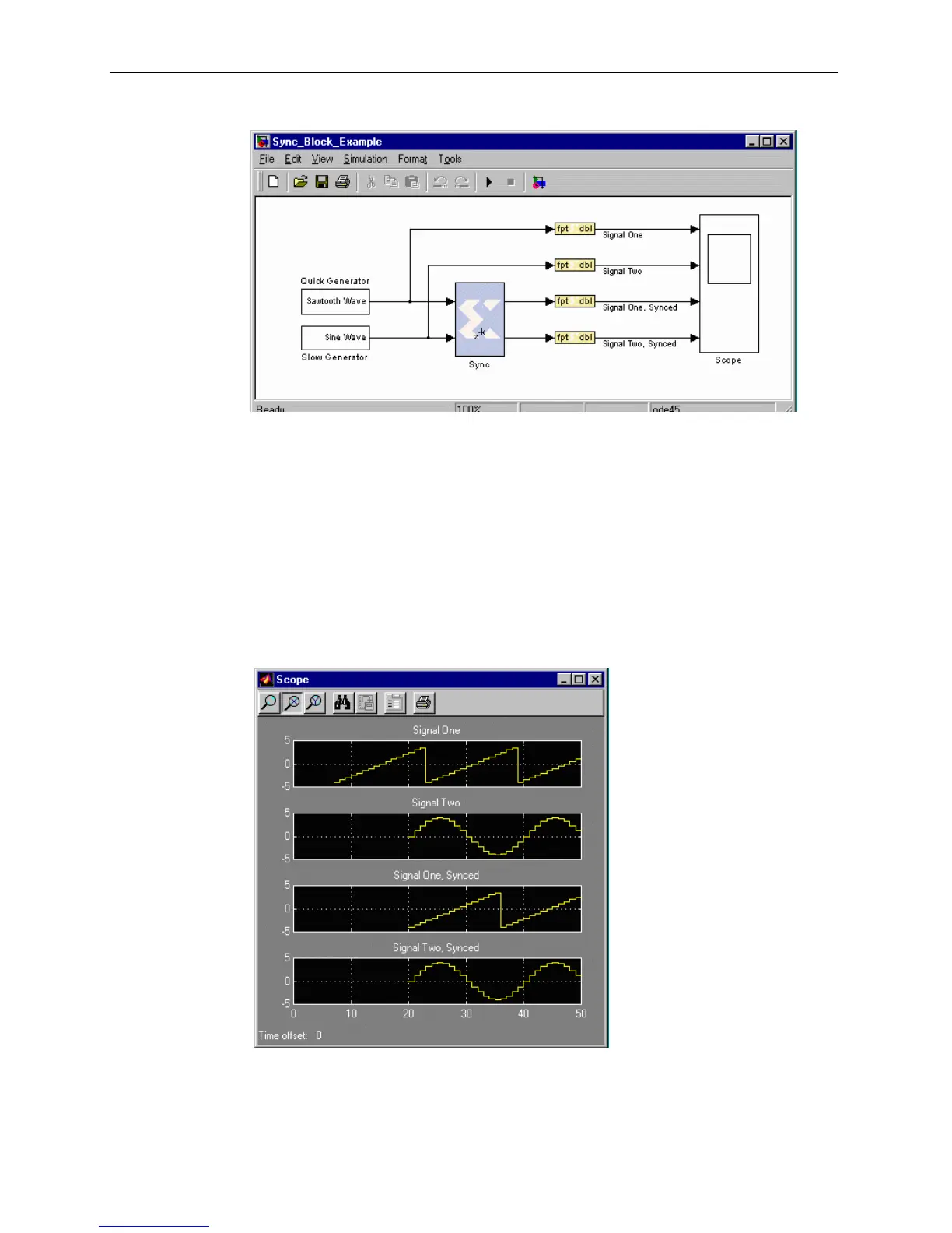
The following diagram illustrates the operation of this block.
Figure 3-23: Sync block use
This diagram shows a two-channel Xilinx Sync Block connected to two signal sources,
with one producing a sawtooth wave and the other a sine wave. The sawtooth
generator is able to produce its output much more quickly than the sine generator.
This scenario could reflect, for example, a CORDIC-based sine generator with many
pipeline stages for hardware efficiency and a simple counter-based sawtooth
generator.
The rest of the diagram shows the connections of both the inputs and outputs of the
Sync block to a four-channel scope. The waveforms presented by that scope are
shown in the figure below. Note that the input waveforms are not aligned, with the
first valid sine wave samples significantly lagging the sawtooth wave. In the third and
fourth scope windows, the output signals can be seen to have been aligned.
Figure 3-24: Output of diagram showing Sync block use