38
1. Unscrew the top aluminum shock cap nut and remove the entire top assembly.
2. Drain the oil from the shock body.
3. Unscrew the end cap from the bottom of the shock body.
4. Clean all of the shock parts thoroughly with electric motor cleaner. Make sure to only use a cleaner that DOES NOT leave a residue.
• For adjustable pistons, open all four piston holes .
• Fill the shock body with cleaner and pump the cleaner through the piston holes three or four times by pushing/pulling the shock rod.
• Dry all of the parts thoroughly.
5. Completely cover both small and large O-rings under the end cap with shock oil and screw on the end cap.
6. Make sure all four holes are open and the piston/rod is at the bottom of the shock body.
7. Hold the shock upright and slightly overfi ll the shock body with shock oil.
8. Air bubble removal:
• Pump the piston once, without letting it come close to the surface of the oil.
• If using adjustable pistons, close and reopen all holes to eject small air bubbles caught between the piston halves.
• Rotate the piston by 1 position.
• Repeat this process 4 or more times.
• Add shock oil as necessary.
• Pull the piston rod most of the way out of the shock body. Let the shock rest for 5 minutes to allow the air bubbles to escape.
9. Membrane and top cap installation:
•Insert the composite upper ball joint into the alu shock cup.
• Insert the shock foam insert into the composite upper ball joint.
• Insert the shock absorber membrane into the alu shock cup.
• After you insert the membrane ensure that it sits properly all around the alu cup properly.
• When installing the shock cap assembly on the shock body, some oil will leak out... this is normal.
• Fully tighten the cap and clean off any excess oil.
• After the shock is assembled, the shock rod will push itself out of the shock body fairly quickly.
NOTE: If the cap nut is not tightened enough, it may unscrew itself when you try to adjust the ride height using the threaded spring collars.
10. Adjusting rebound:
• To set the Shock Rebound, release the shock composite lower cap.
• VERY SLOWLY do the following: Fully pull out the shock rod, push it back in fully, and then fully pull it out once more. Repeat this procedure the
following number of times to achieve the desired Shock Rebound setting:
10 times - approximately 75% rebound (high rebound - suggested for very low traction track)
15 times - approximately 50% rebound (medium rebound - suggested for standard track)
20 times - approximately 25% rebound (low rebound - suggested for very high traction track)
During the Rebound Adjustment procedure shock oil will leak out of the shock body through the O-ring on the shock rod... this is normal. During the
Rebound Adjustment procedure DO NOT open the upper shock cap.
• After you have set the Rebound Adjustment, re-install the shock lower composite cap.
FILL AND BLEEDING PROCESS
TIPS
The most important maintenance task for keeping consistent shock performance is refi lling and bleeding them correctly. If built correctly, it will not be necessary
to re-build them often. Replacing warped/hard rubber bladders and o-rings, scarred piston rods, or shaved/split/loose composite upper and lower ball joints
are also important.
• For club racing, it is recommended to check the shocks for air inside before each race and only re-fi ll and bleed them if necessary. Before each race day,
make sure you take the spring off of each shock, hold it up to your ear, and quickly compress the shock rod fully into the body while listening for any air
making a “whistling” or “squishy” sound as it passes through the piston holes. If you hear any air, refi ll and bleed your shocks. For high competition racing,
it is recommended that the shocks be re-fi lled and bled before a large event.
• If building or pairing new shocks, always make sure they are the same length using a shock length measuring tool and adjust the lower ball joints as
needed.
• If installing new rubber bladders, carefully trim the thin excess rubber from the edges of their lips. Curved body scissors work the best.
LOWER SHOCK BALL JOINT INSTALLATION
SHOCK BUILDING TIPS
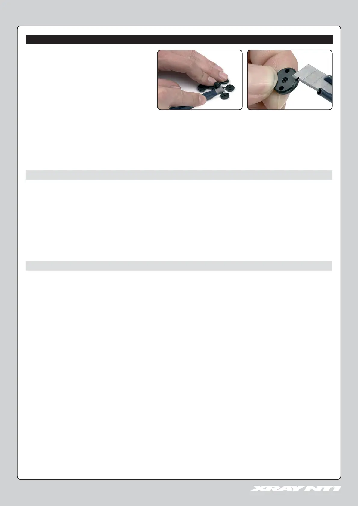
COMPOSITE PARTS PREPARATION
Carefully use a hobby knife (at a perpendicular angle) or
fi ne fi le to gently remove excess composite material from the
outer edge of each piston. This is a critical step; the outer
edges of the shock pistons must be smooth and round.
1. Install the metal pivot ball into the shock lower ball joint.
2. Pre-thread the ball joint using an M3x8 screw.
3. Hold the shock rod with a shockrod clamping tool, or use a pair of side cutters to grip the top groove of the threaded end section. Tighten the ball joint
onto the shock rod. If using side cutters, make sure the fl at side of the wire cutter blades are facing the ball joint. If necessary, use a pair of gripping pliers
(e.g. Vise Grips™) to hold the handles of the side cutters to prevent the shock rod from turning.
4. While gripping the shock rod, screw the ball joint on a few turns with your fi ngers. Then use pliers to clamp the pivot ball inside the ball joint and tighten
the ball joint all the way onto the threads.
PERIODIC SHOCK MAINTENANCE

 Loading...