Specications
Supply Voltage
20 to 30 VDC (24 VDC nominal)
Imager Current Consumption
Nominal (at 24 VDC):
8mA (1 Emitter)
10mA (7 Emitters)
Peak (at 24 VDC) during training mode:
31mA
Emitter Current Consumption
Wired Version (at 24 VDC):
350µA Std Power, 800µA High Power
Battery Version (1.9 - 3.2 VDC):
Built-in 5 Year Replaceable Battery
Field Wiring
Cable Guage
0.2 - 4mm² (26-12 AWG)
Alarm Threshold Levels:
Low - Highest sensitivity / earliest alarm:
20% (0.97 dB)
Medium - Medium sensitivity:
35% (1.87 dB)
High - Lowest sensitivity / maximum
immunity to nuisance smoke conditions:
50% (3.01 dB)
Adjustment Angle
±60° (horizontal)
±15° (vertical)
Maximum Misalignment Angle
±2°
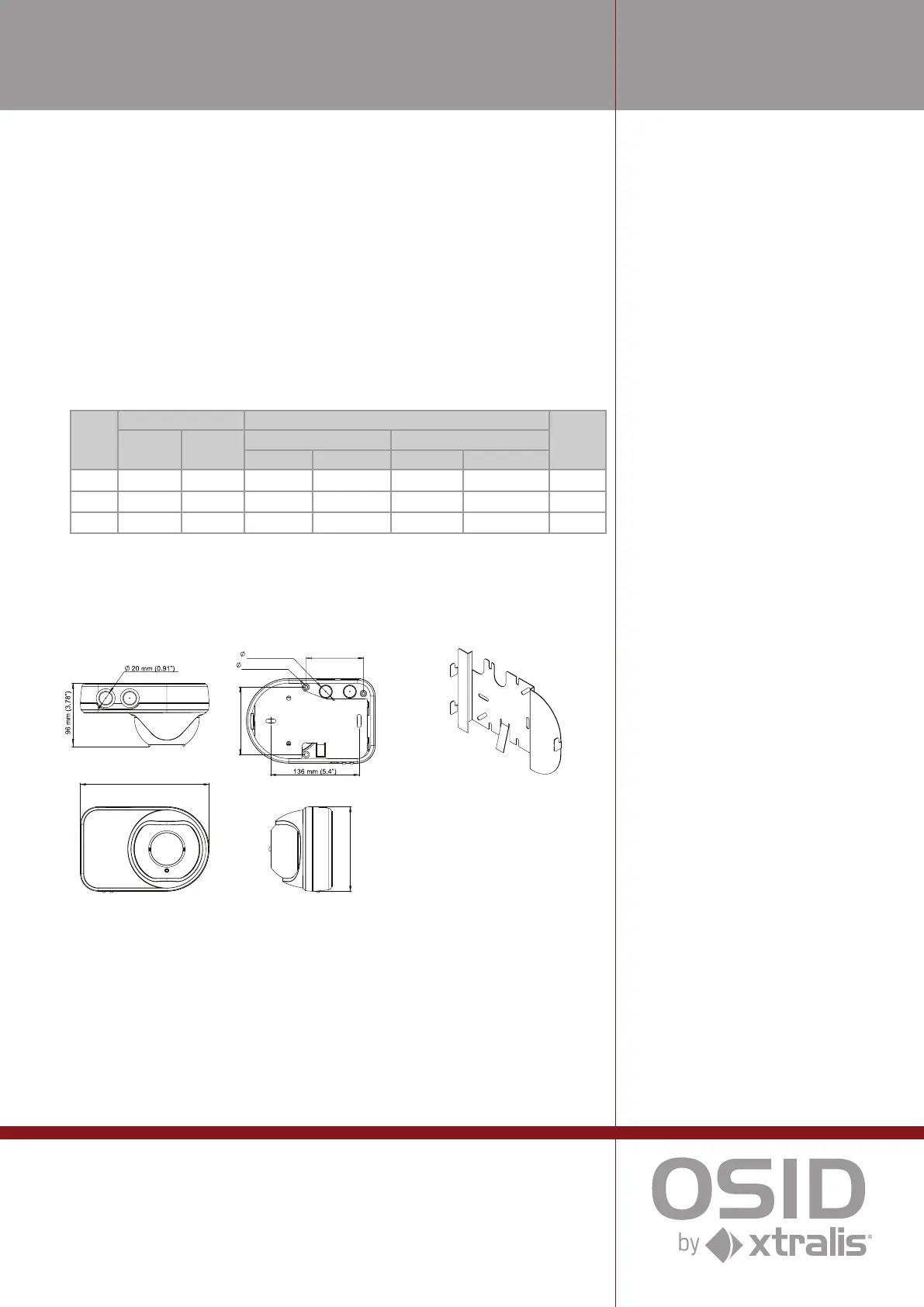
Dimensions (WHD)
Emitter / Imager:
208 mm x 136 mm x 96 mm
(8.19 in. x 5.35 in. x 3.78 in.)
Operating Conditions*
Temperature:
-10 °C to 55 °C (14 °F to 131 °F)*
Humidity:
10 to 95% RH (non-condensing)
Please consult your Xtralis ofce for
operation outside these parameters.
IP Rating
IP 44 for Electronics
IP 66 for Optics Enclosure
Status LEDs
Fire Alarm (Red)
Trouble / Power (Bi-color Yellow / Green)
Event log
10,000 events
Doc. No. 15211_21
The contents of this document are provided on an “as is” basis. No representation or warranty (either express or implied) is made as to the completeness,
accuracy or reliability of the contents of this document. The manufacturer reserves the right to change designs or specications without obligation
and without further notice. Except as otherwise provided, all warranties, express or implied, including without limitation any implied warranties of
merchantability and tness for a particular purpose are expressly excluded.
Xtralis, Xtralis logo, The Sooner You Know, VESDA, ICAM, ECO, OSID, HeiTel, ADPRO, IntrusionTrace, and LoiterTrace are trademarks and/
or registered trademarks of Xtralis and/or its subsidiaries in the United States and/or other countries. Other brand names mentioned herein are for
identication purposes only and may be trademarks of their respective holder(s). Y
our use of this document does not constitute or create a licence or any
other right to use the name and/or trademark and/or label.
This document is subject to copyright owned by Xtralis. You agree not to copy, communicate to the public, adapt, distribute, transfer, sell, modify or
publish any contents of this document without the express prior written consent of Xtralis.
www.xtralis.com
UK and Europe +44 1442 242 330 D-A-CH +49 431 23284 1 The Americas +1 781 740 2223
Middle East +962 6 588 5622 Asia +86 21 5240 0077 Australia and New Zealand +61 3 9936 7000
Part No. 29573
OSID Smoke Detection
On the Imager, a termination card provides all eld wiring terminals, and DIP switches
enable the user to congure the detector for particular applications.
Alignment of the Emitter is simply achieved using a laser alignment tool to rotate the
optical spheres until the laser beam projected from the alignment tool is close to the
Imager.
The Imager is aligned in a similar way so that its Field of View (FOV) encompasses
all Emitters. A Trouble or Fault will be indicated if an Emitter is missing or outside the
Imager eld of view.
The OSID system is highly tolerant to dust and dirt and requires little maintenance in
practice. Preventative maintenance is limited to occasionally cleaning the optical faces
of the detector components.
Conguration Options
OSID systems may be congured to suit a range of detection spaces by selecting the
number of Emitters and type of Imager. Each type of Imager differs by the lens used in
the unit, which determines the eld of view and range of the system.
Imager
Field of View Detection Range Max.
Number
of
Emitters
Horizontal Vertical
Standard Power High Power
Min Max Min Max
10° 7° 4° 30 m (98 ft) 150 m (492 ft) - - - - 1
45° 38° 19° 15 m (49 ft) 60 m (197 ft) 30 m (98 ft) 120 m (393 ft) 7
90° 80° 48° 6 m (20 ft) **34 m (111 ft) 12 m (39 ft) **68 m (223 ft) 7
** Maximum Distances measured for the Center Field of View of the Imager. For more details on distances for the
Imager, see the OSID Product Guide.
Emitter / Imager Dimensions
Ordering Codes
OSI-10 Imager - 7º coverage OSE-HPW Emitter - High Power, Wired
OSI-45 Imager - 38º coverage OSID-INST OSID Installation Kit
OSI-90 Imager - 80º coverage OSP-001 FTDI Cable 1.5m
OSE-SP-01 Emitter - Alkaline Battery OSP-002 Laser Alignment tool
OSE-SPW Emitter - Standard Power, Wired OSID-WG Wire Guard
OSID-EHE Emitter environmental housing IP66 OSE-RBA Spare alkaline battery pack for Emitter units
OSID-EHI Imager environmental housing IP66 OSE-RBL Replacement Lithium Ion Kit
OSE-ACF Anti-condensation lm for Emitters
OSEH-ACF Anti-condensation lm for OSID-
EHE and OSID-EHI environmental
housings
Approvals Compliance
Please refer to the Product Guide for
details regarding compliant design,
installation and commissioning.
* Product UL listed for use from 0°C to 39°C (32°F to 103°F)
164.6°
80
99.9
7.100
116
B
208 mm (8.2”)
136 mm (5.4”)
20mm (0.8”)
90mm (3.5”)
106mm (4.2”)
4mm (0.16”)

 Loading...


