This document, the "ICAM Commissioning Guide," outlines the process for commissioning an ICAM (Intelligent Control and Monitoring) system. It is intended for individuals who have attended accredited ICAM training and are knowledgeable about the ICAM product range, aspirating smoke detection systems, and relevant local codes and standards. Commissioning involves integrating the pipe network design, detector installation, power and communication cabling, and system power-up to deliver a fully functional ICAM system that meets customer specifications.
The commissioning process is a systematic approach to validate all operational aspects of the ICAM system, benchmark performance levels, and generate necessary documentation for effective management and maintenance. It is divided into several stages:
Pre-Commissioning:
This stage is split into two parts: tasks performed before visiting the customer site and tasks performed once on site.
Before visiting the site, the commissioning engineer should gather and study design and installation records, including:
- Site layout plans
- "As Installed" drawings
- Pipe network design records
- Pipe network installation record
- Relevant product and installation guides
- A set of ICAM commissioning forms (Xtralis document number 16022)
- Any other forms required by local codes and standards
- A PC/Laptop with Xtralis VSC software and a Serial lead (9-pin null modem cable) for configuration. An RS232 to USB converter is needed if the PC/Laptop lacks a serial port.
- Material for conducting an acceptable smoke test (refer to Section 5.1).
- Optional: A digital manometer for measuring sample hole pressure (Max range 3kpa for Wide Bore networks, 0.20kpa for Narrow Bore networks with Microbore Tube).
The engineer must also be aware of local codes and standards. During this stage, client and site details should be completed in the Commissioning Forms, including Customer Name, Site address, Installer's Name and Address, Type of Installation, and the engineer's name and address. Commissioning Forms are available in ASPIRE for supported detectors.
Once on site, the initial steps involve checking cabling and initial power-up. All electrical and ICAM network cabling must be securely terminated with correct polarity. The system should be connected to a 24 VDC power source.
Caution: Reversing the supply or providing out-of-specification power can damage the ICAM system.
All electrical installations must meet local electrical codes and standards. Data communication uses an RS 485 network (unidirectional), requiring correct polarity throughout. Belden 9841 (120 ohm) twisted pair cables (or similar) are recommended.
Upon power-up, the system takes approximately 30 seconds to initialize. If any detector fails to power up, power connections and polarity should be re-checked.
During power-up, different detectors exhibit specific behaviors:
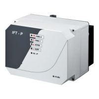
- IFT detectors: Sounder beeps, aspirator starts, display shows a rolling test message (type, software version, optional text), fault indicators activate for current faults, current smoke background level (%obs/m) is displayed, and the Power LED turns on if no faults exist.
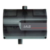
- IAS detectors: All LEDs turn on then off, aspirator starts, fault indicators activate for current faults, high and low flow thresholds and current flow level are indicated on the bargraph, and the System OK LED turns on if no faults exist.
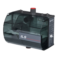
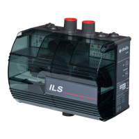
- ILS detectors: All LEDs turn on then off about five times with sounder beeps, aspirator starts, fault indicators activate for current faults, smoke levels are indicated on the bargraph, and the System OK LED turns on if no faults exist.
Detectors may show faults immediately after power-up, which is normal. Resetting the detector(s) unlatches relays and fault LEDs. If issues persist, refer to the product guide for correct installation.
A preliminary systems check using Xtralis VSC software should be conducted. Faults generated at power-up or due to site changes are normal and can be silenced by accepting factory defaults, but detectors must be configured to site requirements. Settings should be changed to suit site requirements, including normalizing airflow using Xtralis VSC or the display panel. A smoke test at the farthest sampling hole confirms the detector registers smoke within ASPIRE's anticipated time and local codes' maximum time, checking for blockages or leakages.
System Configuration and Setting Thresholds:
ICAM detectors (except IAS detectors) are recommended to be configured with Xtralis VSC software. If VSC is unavailable, a display panel can be used. IAS detectors can only be configured via their user interface. Airflow and smoke alarm thresholds should ideally be determined using ASPIRE pipe network configuration software. Upon first power-up, Xtralis VSC registers all ICAM detectors as unconfigured, with other products appearing under ancillary devices. Detailed explanations for Xtralis VSC software and detector setup via display panel are available in the online help and relevant product guides.
IFT Detector Configuration:
Key functions for IFT systems with a connected display panel include:
- Main Menu Modes: Accessed by pressing MENU, navigating with UP & DOWN (SCAN/ISOLATE) buttons, pressing ENTER (SOUNDER SILENCE), entering the Access Code with Value UP & DOWN (RESET/ACCEPT) buttons, and pressing ENTER. Access Code Entry can be aborted with MENU. All settings can also be entered via Xtralis VSC software. The RS232 port requires cover removal and replacement for 60 minutes before flow normalization.
- Access Codes: Several levels of access exist (Operator, Level 1, Level 2, Level 3). Access is downwards applicable. Default codes are: Operator (0 = not required), Level 1 (260), Level 2 (693), Level 3 (Factory Use Only). Access codes are entered using ACCEPT and RESET as UP and DOWN buttons to input a 3-digit number, with flashing digits indicating the active position.
- Programmable Functions (Minimum Access Code Required: Level 2 for some):
- Setting Units: Display resolution for obscuration, language, imperial/metric units are set in the SETUP menu.
- Setting Time and Date (Level 1): Configured via TIME DATE menu.
- Setting IP Address and Mask (Level 1): Configured via WEB menu after Level 1 login.
- Setting Modbus Address (Level 1): Set via CONFIGURE menu (ADDRESS parameter), ensuring uniqueness.
- Setting Air Flows (Level 1): Configured via CONFIGURE menu. Key parameters include FLOWDEL (Flow Fault Delay, 1-60s), FLOWHI/FLOWLO (High/low air flow limits, 0-200%), and SETFAN (Fan Speed, 3-10).
- Setting Smoke Thresholds (Level 1): Day and night smoke thresholds, trace, and delay settings for each sector are set via SECTORS ALMS menu. Day/Night start times are accessed via CONFIGURE menu (NIGHSTART/NIGHSTOP).
- Setting GPI Function (Level 2): 'Remote reset' input can be configured for reset or isolate via RES-ISOL parameter in SETUP menu.
- Setting Up I/O Modules (Level 2 for module type, Level 1 for parameters): Module type configured in SETUP menu. Specific parameters via CONFIGURE menu. Refer to IFT Product Guide for details.
ILS Detector Configuration:
Key functions for ILS detectors:
- Programmable Functions: Configured via user interface panel or Xtralis VSC software.
- Navigating User Interface: Press and hold SELECT and CHANGE keys simultaneously for 1 sec to initialize function selection. Press and release SELECT to step through functions, CHANGE to modify settings. Relevant LED flashes indicate selected function.
- Enabling Updates: Enter 3-digit access code (510). Numbers are selected sequentially by pressing CHANGE to illuminate the number LED, then SELECT. CODE LED flashes, UNLOCK LED illuminates on success.
- Programmable Functions: Modify functions via detector setup: Reset/Isolate system, Set fan speed, Set sensitivity of bar graph to airflow changes, Set flow delay time, Set high/low flow fault thresholds, Set Alert/Action/Fire alarm Thresholds, Set detector mode (ILS only), Turn Sounder on/off, Set Alarm Latching, Normalize airflow. Pressing SELECT for >1 sec when unlocked reverts to normal operating mode.
IAS Detector Configuration:
Key functions for IAS detectors:
- Programmable Functions: Configured via user interface panel or Xtralis VSC software. Only airflow parameters are configurable as point detectors are wired directly to the fire alarm control panel.
- Navigating User Interface: Same as ILS detectors.
- Enabling Updates: Same as ILS detectors (access code 510).
- Programmable Functions: Modify functions via detector setup: Set fan speed, Set sensitivity of bar graph to airflow changes, Set high/low flow fault thresholds, Set flow delay time, Normalize airflow. Pressing SELECT for >1 sec when unlocked reverts to normal operating mode.
System Integrity Test:
ICAM systems can be tested in various ways, depending on customer environment and local codes/standards. Local codes may override ICAM suggestions. Performance testing is done during commissioning and may be required during service, but pipe integrity testing is highly recommended annually.
Note: Some tests generate significant smoke, requiring precautions.
This test proves pipe network integrity and measures response time. The type of test depends on the site and application:
- Warehouses/open areas: Smoke pellet test, polyurethane mat test, or wooden block test. Check local codes.
- Very sensitive sites: Electrical overload (PVC coated wire burn test) or smouldering test coil test (UK customers refer to BS 6266, BFPSA Code of Practice Appendix A).
At least two tests are recommended, allowing the environment to return to normal conditions between tests. Record date and type of test on commissioning forms. Refer to detector manuals for interpreting smoke levels (Alert, Alarm, Fire1).
Minimum testing requires pipe integrity smoke testing.
Testing and Stratification Problems:
In high-roof areas, warmer air near the roof can cause smoke stratification, preventing smoke from reaching roof-mounted sample points. To counteract this, a larger distance between the roof and the sampling point may be needed as roof height increases. Standard 25 mm (1 in.) standoffs are suitable for heights up to 3 m (9 ft). For higher roofs, distances increase: 100mm for 4m, 200mm for 5m, 300mm for 6m, 400mm for 7m, 500mm for 8m, 600mm for 9m. A 5.8 kW gas burner or electric heater can be used to add heat to the smoke to ensure it reaches the roof.
Pipe Integrity Smoke Testing:
This method is for standard sensitivity fire detection systems in typical customer sites. It requires a smoke source, stopwatch, and fire extinguisher. Detectors with display modules show increased smoke levels.
- Isolate local fire panel and automatic extinguishing/suppressant systems.
- Introduce smoke directly into the furthest sample hole and start timer.
- Stop timer when detector registers smoke and record results.
- Compare actual time with ASPIRE's expected time. If actual time is 20% or greater than expected, check for pipe breaks.
Smoke Pellet Testing:
Suitable for high and enhanced sensitivity environments. Requires smoke pellets, a tray, and a timer. A radiated heater may be needed for high-roof areas to fix stratification.
- Isolate local fire panel and automatic extinguishing/suppressant systems.
- Cover a metal tray with kitchen foil.
- Set heater close to the tray to make smoke rise.
- Place smoke pellets on the tray (number determined by system designer).
- Place protection under the tray.
- If testing in a high-roof area, turn on the heater.
- Light pellets with a match and start timer.
- Acceptable response time is specified by local codes/standards or system design.
For more information, refer to BFPSA or FIA CoP standards.
Polyurethane Mat Smoke Testing:
Suitable for standard sensitivity fire detection systems. Involves lighting a flexible polyurethane foam mat. This test is for open areas like warehouses and atriums.
Warning: Burning polyurethane foam generates toxic gases. Use appropriate protective equipment.
- Isolate local fire panel and automatic extinguishing/suppressant systems.
- Cover a metal tray with kitchen foil.
- Place mat(s) in the tray (multiple mats as required by designer).
- Place protection under the tray.
- Ignite a corner of the mat with a match and start stopwatch.
- Acceptable detector response time is specified by local codes/standards or system design.
Legend: A = 500mm (20 in), B = Kitchen foil in tray, C = 20mm (0.874 in).
Wire Burn Smoke Testing:
This test simulates early fire stages for high sensitivity fire detection systems, suitable for underfloor spaces or ceiling voids. It involves overloading a 1-meter length of PVC-coated wire (10/0.1 mm strands, 0.3 mm radial thickness, 0.078 mm² conductor area) using a transformer. Xtralis offers a VTT-10000 test kit.
Warning: Burning PVC coating is harmful. Do not hold the wire. Remotely turn on the transformer and use appropriate protective equipment.
- Isolate local fire panel and automatic extinguishing/suppressant systems.
- With power off, connect each end of a 1-meter (3 ft.) specified wire to the VTT-10000.
- Lay wire on an insulating board to prevent floor damage.
- Check for kinks or crossovers in the wire.
- Connect power to VTT-10000 and turn on for 60 seconds. 6 VAC is applied, the switch illuminates, and the green timer indicator flashes. The wire heats up, generating a small amount of smoke.
- Turn off the unit after the timed burn period.
- Record detector response time.
- For multiple tests, allow 5 minutes (300 seconds) between tests for smoke dissipation.
Caution: Test wires become very hot. Do not touch.
Note: For denser smoke in large spaces or strong ventilation, two 1m wire test kits can be used.
Record the following on the commissioning form:
- Transport Time: Time for smoke to travel from the furthest sampling hole to the detector. Wide variations from ASPIRE predictions indicate leaks, blockages, or mismatch between installed pipe network and model.
- Initial Response: Total time for smoke to travel to sampling point and detector to first register smoke (excluding alarm delays).
- Alert Response: Time for initial response and detector to generate an Alert Alarm.
- Action/Pre-Alarm: Time for alert and detector to generate an Action/Pre-Alarm status (excluding delays).
- Fire 1/Fire Response: Time for alert and detector to generate a Fire 1/Fire Response status (excluding delays).
- Fire 2 Response: Time for alert and detector to generate a Fire 2/Fire Response status (excluding delays).
- Peak Smoke Response: Time for detector to record peak smoke level (excluding delays). Numerical display/LCD Programmer shows smoke levels; information also extractable from event log.
Acceptable response times are determined by site requirements, local codes, and standards. If test response times don't meet standards, the commissioning form should be signed as "NOT ACCEPTABLE," with recommendations for further work recorded.
Testing Devices:
Outputs for IFT detectors can be tested using a diagnostic test accessed via the TEST OUTPUTS menu function. Refer to the IFT Product Guide for details.
Documenting Test Results:
Test results must be recorded on ICAM commissioning forms. Once completed and signed, forms and attachments should be forwarded to all relevant parties mentioned in Chapter 6. Copies of commissioning forms are available in the document library at www.xtralis.com (Xtralis document number 16022).
Hand Over:
Both the engineer and customer must be satisfied that all commissioning aspects meet required standards and the system is ready for day-to-day operation. To hand over the system:
- Ensure ICAM commissioning forms are complete and all relevant sections filled.
- If Xtralis VSC was used, select Device or Address, then File | Print to print configuration details and include with hand over documents.
- Obtain relevant signatures.
- Ensure relevant attachments are included with the commissioning form.
- Make copies of completed forms and attachments and forward to: Appropriate Xtralis Sales Office, Installing contractor, Designer of the system, and End user of the system.