Do you have a question about the Xtralis ICAM IFT-P and is the answer not in the manual?
Provides contact details for Xtralis support across different geographical regions.
Information on the ICAM product's compliance with FDA laser product regulations.
Safety warnings and precautions related to the laser chamber of the detector.
Details specific requirements and sensitivity ranges for UL and ULC standards.
Explains EN54-20 sensitivity and flow monitoring requirements for the product.
Lists various certifications and approvals obtained by the ICAM IFT-P detector.
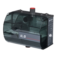
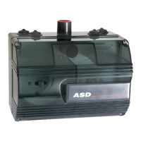
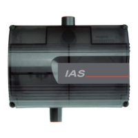
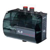
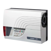
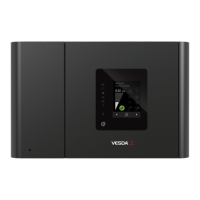
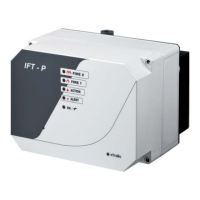
Overview of the ICAM IFT-P detector and its function as an aspirating smoke detector.
Explains how air samples are drawn, processed, and detected using a laser chamber.
Describes how the system monitors pipe network air flow for blockages or disconnections.
Details the default settings for the four alarm states: Alert, Action, Fire 1, and Fire 2.
Explains the function of the LEDs on the detector's display panel for status indication.
Outlines the methods for connecting the detector to a PC for configuration and monitoring.
Guidelines for selecting appropriate mounting locations for the detector unit.
Covers detector power supply, I/O modules, and Ethernet cable connections.
Provides guidelines and specifications for attaching the air sampling pipe network.
Procedure for powering up the system and initial checks after installation.
Details how to configure the detector using software or a remote display unit.
Steps for routine inspection of the detector and control panel for faults.
Information on recommended servicing intervals and tests for the detector.
Details supply voltage, power consumption, and capacitive loading for the detector.
Provides physical dimensions and IP rating for the detector's enclosure.
Specifies ambient temperature, humidity, and sampled air conditions for operation.
Defines pipe size, length, and area coverage for the air sampling network.
Details power input and relay outputs available on the detector.
Covers alarm sensitivity ranges and programmable levels for different alarm states.
Lists supported communication protocols like RS232, RS485, and TCP/IP.
Describes the configuration and usage of the 4-channel relay module.
Details the specifications and configuration of the 8-channel analog output module.
Specifies wiring requirements for UL/ULC fire alarm connection applications.
Covers cabling requirements and electrical supply for the Remote Display Unit.
Provides a guide to navigating the menus and functions of the Remote Display Unit.
Explains the functions of the buttons on the Remote Display Unit, including access codes.
Displays a list of current faults not already indicated on the Remote Display Unit LED.
Enables operator functions like Isolate, Sounder Silence, and Reset.
Allows inspection of engineering values for diagnostic purposes.
Enables modification of detector configuration parameters and settings.
Resets all configuration parameters to their factory default values.
Allows inspection of various maintenance parameters and system status.
Enables manual simulation of fire events to test detector responses and alarms.
Defines obscuration levels for day and night alarm events across different sectors.
Procedure for setting the detector's IP address and subnet mask via the web interface.
Details parameters like resolution, remote panel operation, and country code settings.
| Brand | Xtralis |
|---|---|
| Model | ICAM IFT-P |
| Category | Smoke Alarm |
| Language | English |