ICAM by Xtralis
ICAMIFT-PProduct Guide
www.xtralis.com 5
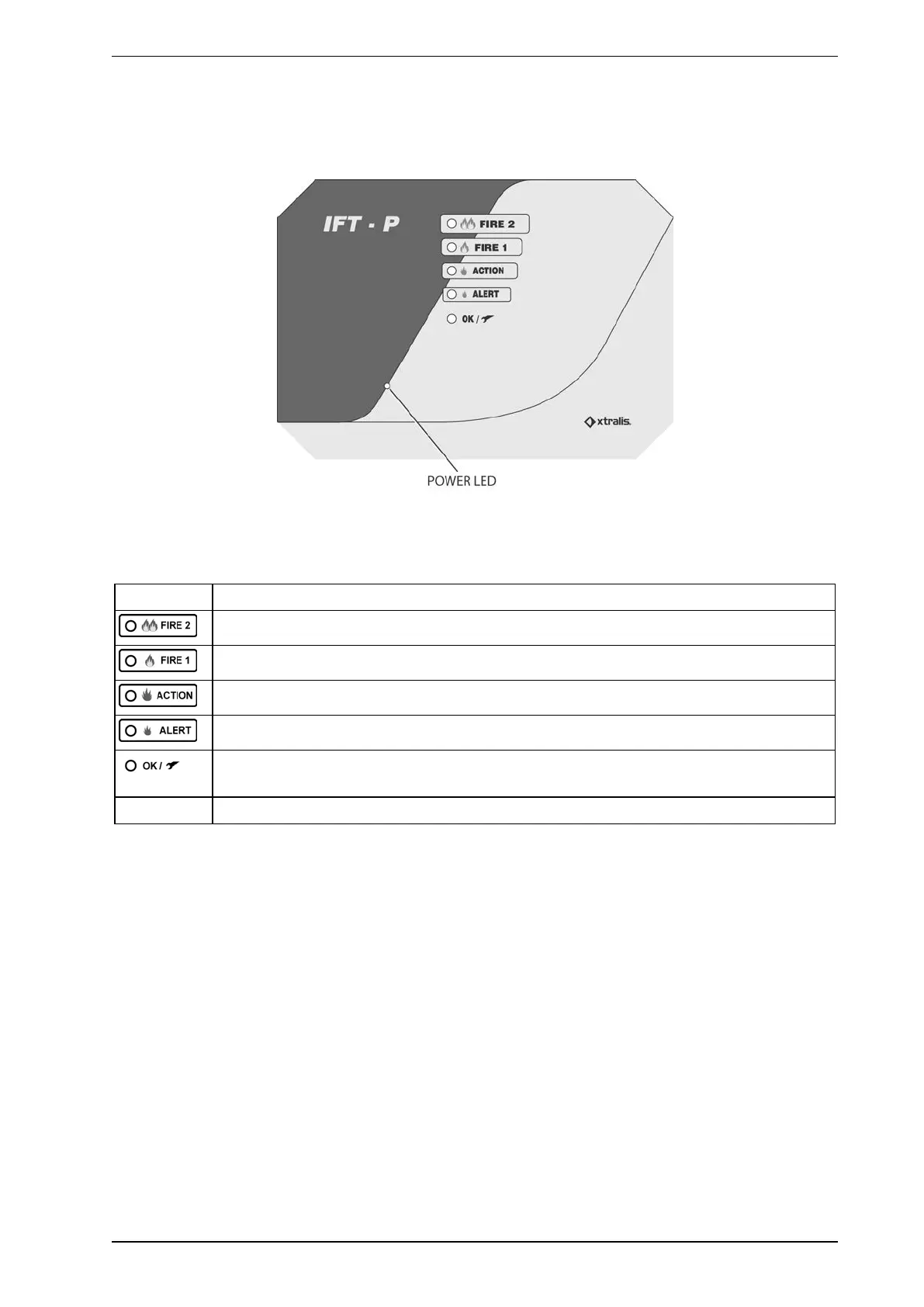
1.5 Detector Display Panel
The display panel has LEDs to indicate the Action and Fire 1 alarm states, OK / Fault conditions and power
status.
Figure 1-2: Display Panel
The following table describes the display panel LEDs.
Table 1-2: LED Descriptions
LED Description
This Red LED is activated when the Fire 2 alarm threshold is exceeded.
This Red LED is activated when the Fire 1 alarm threshold is exceeded.
This Red LED is activated when the Action alarm threshold is exceeded.
This Red LED is activated when the Alert alarm threshold is exceeded.
This bi-color LED is Green when there is no fault, and Yellow when fault condition is
detected.
Power LED This Blue LED is activated when POWER is supplied to the detector.
1.6 Communications Interface
ICAM IFT-P detectors can connect to a PC with Xtralis VSC or VSM4 software via Ethernet, through a
RS232 direct serial connection or with RS485 via a RS485/RS232 converter. More details may be found in the
ICAM Communications Guide.
 Loading...