Do you have a question about the Xtralis ICAM IAS-1 and is the answer not in the manual?
Explains bold and italics usage for emphasis, names, and references within the document.
Describes the meaning of caution and warning icons used throughout the document to indicate dangers.
Discusses reading the document with local codes and standards, and the precedence of local codes.
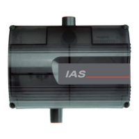
Introduces the Xtralis ICAM IAS-1 aspirating smoke detection system and its air-sampling pipe network.
Details the process for mounting the unit, including using tools and ensuring correct fasteners for the surface.
Illustrates field connectors for an IAS-1 detector, showing power supply, fuse, and loop/fault wiring interfaces.
Explains the use of baffles to direct sampled air flow towards the detector for optimal performance.
Details attaching point detectors to the mounting board and connecting their wiring.
Provides typical wiring examples for conventional and analog addressable detectors.
Details requirements for pipe material, color, markings, and airtight seals for AS 1603.8 compliance.
Outlines common pipe fixing methods like clips, clamps, or tie wraps, with typical fixing center distances.
Explains perforation of sampling pipe with holes, avoiding swarf, and placement for smoke intake.
Describes the function and configuration of the end cap with a central hole for pipe termination.
Specifies the use of swept bends (45° or 90°) to minimize pressure loss and response time.
Discusses options for connecting pipe to the exhaust port to divert air and potential limitations.
Explains the role of the filter element in the sampled air path and when additional filtration may be needed.
Presents standard pipe network designs for IAS-1 systems, including single pipe and tee configurations.
Illustrates an example of an IAS-1 system using a single sampling pipe.
Shows an example of an IAS-1 system using a tee with two sampling pipes, detailing length and balance.
Explains the meaning of icons and indicators on the IAS-1 system display, including bargraph and status LEDs.
Describes how to navigate and use the system's user functions for setting fan speed, sensitivity, and calibration.
Provides guidelines for setting fan speed, flow limits, and flow delays prior to calibration and testing.
Advises on setting fan speed for optimal transport time, balancing performance with power requirements.
Explains default flow delay settings and how to adjust them for environments with fluctuating conditions.
Details how to set system responsiveness for reporting blocked sampling points or broken pipes.
Describes methods for testing detector alarm functionality and reporting low flow faults.
Details how to perform a system check, introducing smoke to sampling points and verifying compliance.
Provides step-by-step instructions for replacing the filter element to maintain system performance.
Discusses pre-engineered pipe network designs, constraints, and key parameters for optimal system performance.
Offers solutions for common problems encountered with the IAS-1 system, covering power, display, fan, and flow issues.
Provides a table of typical current consumption figures corresponding to different fan speeds.
| Type | Aspirating Smoke Detector |
|---|---|
| IP Rating | IP30 |
| Operating Temperature | -10°C to +55°C |
| Detection Method | Laser-based particle detection |
| Alarm Sensitivity Range | 0.001% obs/m to 20% obs/m |
| Supply Voltage | 18 to 30 VDC |
| Alarm Threshold | Adjustable |
| Response Time | Adjustable |
| Humidity Range | 10% to 95% non-condensing |
| Communication | RS-485 |
| Certifications | EN 54-20, UL 268 |
| Aspiration Tubing | Up to 100 m (328 ft) total length |