Ducts Application Note VESDA-E
35424_02 4
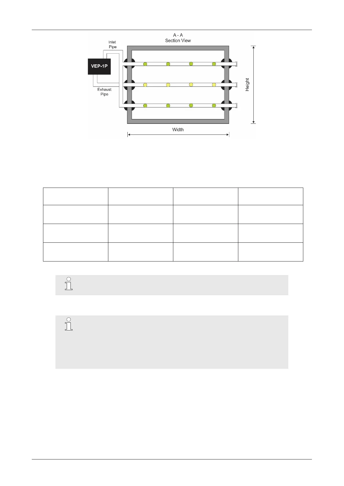
Figure 6: Cross-section view of the inlet pipe
sampling hole setup and exhaust pipe in large ducts.
Table 2: Sampling hole requirements for a VESDA-E VEP-1P detector with 5 m (16.4 ft) inlet pipes
and 2 m (6.56 ft) exhaust pipe in a large duct.
Rate (L/min) {cfm}
{
9
/
64
}
{
1
/
8
}
{
1
/
8
}
Nominal sampling hole spacing is 0.4 m (1.3 ft).
The exhaust pipe must have 4 × Ø10 mm (13/32 inch) sampling holes, regardless of the width of the duct.
These holes should be located in the middle of the duct width at least 50 mm (2 inches) from the side walls.
Calculations, performed with the ASPIRE pipe design software tool and
shown in Tables 1 and 2, apply to a 5 m (16.4 ft) inlet pipe and a 2 m (6.56 ft)
exhaust pipe. These calculations are suitable for an inlet pipe length of 1 to 10
m (3.28 to 32.8 ft) and an exhaust pipe length of < 2 m (6.56 ft), provided that
corresponding pipe flow rate adjustments are made. Always refer to local
codes and standards for hole size and spacing requirements.