Part Description
2 Entrance flange
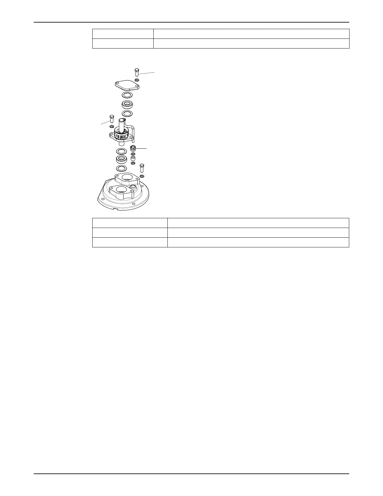
Figure 7: Cable entry for version code 2201.012 MT and 2201.020 LT
Part Description
1 Screws
2 Gland nut
Figure 8: Cable entry for version code 2201.320
1. Check the data plate to see which connections are required for the power supply:
• Y
• D
• Y serial
• Y parallel
• Y/D
2. Arrange the connections on the terminal board in accordance with the required
power supply.
Do not use links (jumper strips) with the Y/D start.
Do not use links (jumper strips) with the 9 stator leads tandem-coupling.
3. Connect the motor conductors (U1, V1, W1) to the terminal board. Connect the
ground (earth) lead.
4. Make sure that the pump is correctly connected to ground (earth).
5. Make sure that any thermal contacts incorporated in the pump are properly
connected to the terminal board.
6. Install the cover.
7. Version code 2190.010, 2201.012/020: Fasten the screws on the entrance flange so
that the cable insertion assembly bottoms out.
8. Version code 2201.320: Fasten the screws and the gland nut on the entrance flange
so that the cable insertion assembly bottoms out.
After you have connected the motor cable to the pump, connect the motor cable and the
control cable to the starter equipment.
4 Installation
Flygt 2190, 2201 Installation, Operation, and Maintenance Manual 21
 Loading...